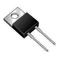
MBR20H100CTG-E3/45 Vishay, MBR20H100CTG-E3/45 Datasheet - Page 2

MBR20H100CTG-E3/45
Manufacturer Part Number
MBR20H100CTG-E3/45
Description
DIODE SCHOTT 20A 100V DUAL TO220
Manufacturer
Vishay
Specifications of MBR20H100CTG-E3/45
Voltage - Forward (vf) (max) @ If
840mV @ 20A
Current - Reverse Leakage @ Vr
100µA @ 100V
Current - Average Rectified (io) (per Diode)
10A
Voltage - Dc Reverse (vr) (max)
100V
Diode Type
Schottky
Speed
Fast Recovery =< 500ns, > 200mA (Io)
Diode Configuration
1 Pair Common Cathode
Mounting Type
Through Hole
Package / Case
TO-220-3 (Straight Leads)
Product
Schottky Diodes
Peak Reverse Voltage
100 V
Forward Continuous Current
20 A
Max Surge Current
150 A
Configuration
Dual Common Cathode
Forward Voltage Drop
0.93 V
Maximum Reverse Leakage Current
3.5 uA
Operating Temperature Range
- 65 C to + 175 C
Mounting Style
Through Hole
Lead Free Status / RoHS Status
Lead free / RoHS Compliant
Reverse Recovery Time (trr)
-
Lead Free Status / RoHS Status
Lead free / RoHS Compliant, Lead free / RoHS Compliant
Available stocks
Company
Part Number
Manufacturer
Quantity
Price
Part Number:
MBR20H100CTG-E3/45
Manufacturer:
VISHAY/威世
Quantity:
20 000
MBR20H90CTG & MBR20H100CTG
Vishay General Semiconductor
Note:
(1) Pulse test: 300 µs pulse width, 1 % duty cycle
Note:
(1) Automotive grade AEC Q101 qualified
RATINGS AND CHARACTERISTICS CURVES
(T
www.vishay.com
2
ELECTRICAL CHARACTERISTICS (T
PARAMETER
Maximum instantaneous forward voltage per diode
Maximum reverse current per diode at working peak
reverse voltage
THERMAL CHARACTERISTICS (T
PARAMETER
Typical thermal resistance per diode
ORDERING INFORMATION (Example)
PACKAGE
TO-220AB
TO-220AB
A
= 25 °C unless otherwise noted)
24
20
16
12
8
4
0
0
25
Figure 1. Forward Derating Curve
(1)
MBR20H100CTG-E3/45
MBR20H100CTGHE3/45
50
Case Temperature (°C)
PREFERRED P/N
75
PDD-Americas@vishay.com, PDD-Asia@vishay.com, PDD-Europe@vishay.com
For technical questions within your region, please contact one of the following:
100
125
(1)
150
UNIT WEIGHT (G)
(1)
C
= 25 °C unless otherwise noted)
175
C
I
I
I
I
1.85
1.85
F
F
F
F
= 25 °C unless otherwise noted)
= 10 A
= 10 A
= 20 A
= 20 A
TEST CONDITIONS
T
T
T
T
T
T
PACKAGE CODE
SYMBOL
J
J
J
J
J
J
= 125 °C
= 125 °C
= 125 °C
= 25 °C
= 25 °C
= 25 °C
R
θJC
45
45
Figure 2. Maximum Non-Repetitive Peak Forward Surge
175
150
125
100
75
50
25
1
SYMBOL
V
I
R
F
BASE QUANTITY
Number of Cycles at 60 Hz
Current Per Diode
50/tube
50/tube
TYP.
0.80
0.64
0.87
0.74
-
-
MBR
T
8.3 ms Single Half Sine-Wave
2.0
J
10
= T
J
Max.
Document Number: 88856
MAX.
0.85
0.70
0.93
0.80
DELIVERY MODE
3.5
4.5
Revision: 25-Mar-08
Tube
Tube
100
UNIT
UNIT
°C/W
mA
µA
V


