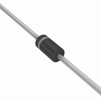
MBR160G ON Semiconductor, MBR160G Datasheet - Page 4

MBR160G
Manufacturer Part Number
MBR160G
Description
DIODE SCHOTTKY 1A 60V DO-41
Manufacturer
ON Semiconductor
Specifications of MBR160G
Voltage - Forward (vf) (max) @ If
750mV @ 1A
Voltage - Dc Reverse (vr) (max)
60V
Current - Average Rectified (io)
1A
Current - Reverse Leakage @ Vr
500µA @ 60V
Diode Type
Schottky
Speed
Fast Recovery =< 500ns, > 200mA (Io)
Mounting Type
Through Hole
Package / Case
DO-204AL, DO-41, Axial
Product
Schottky Diodes
Peak Reverse Voltage
60 V
Forward Continuous Current
1 A @ Ta=55C
Max Surge Current
25 A
Configuration
Single
Forward Voltage Drop
1 V @ 3 A
Maximum Reverse Leakage Current
500 uA
Operating Temperature Range
- 65 C to + 150 C
Mounting Style
Through Hole
Current, Forward
1 A
Current, Reverse
5 mA
Current, Surge
25 A
Package Type
DO-41
Primary Type
Schottky Barrier
Temperature, Junction, Maximum
+150 °C
Temperature, Operating
-65 to +150 °C
Voltage, Forward
1 V
Voltage, Reverse
60 V
Lead Free Status / RoHS Status
Lead free / RoHS Compliant
Reverse Recovery Time (trr)
-
Capacitance @ Vr, F
-
Lead Free Status / Rohs Status
Lead free / RoHS Compliant
Other names
MBR160G
MBR160GOS
MBR160GOS
Available stocks
Company
Part Number
Manufacturer
Quantity
Price
É É É É É É É É
É É É É É É É É
resistance for any mounting configuration to be found. For
a given total lead length, lowest values occur when one side
of the rectifier is brought as close as possible to the heatsink.
Terms in the model signify:
T
T
R
R
R
P
†For information on tape and reel specifications, including part orientation and tape sizes, please refer to our Tape and Reel Packaging
*This package is inherently Pb−Free.
ORDERING INFORMATION
Specifications Brochure, BRD8011/D.
A
D
L
qS
qL
qJ
MBR150
MBR150G
MBR150RL
MBR150RLG
MBR160
MBR160G
MBR160RL
MBR160RLG
Use of the above model permits junction to lead thermal
= Lead Temperature
= Ambient Temperature T
= Power Dissipation
= Thermal Resistance, Junction−to−Case
VECTOR PIN MOUNTING
= Thermal Resistance, Heatsink−to−Ambient
= Thermal Resistance, Lead−to−Heatsink
Mounting Method 1
P.C. Board with
1−1/2″ x 1−1/2″
copper surface.
L
L
Mounting Method 2
L
L
Device
T
É É
É
É
É
C
J
= Junction Temperature
= Case Temperature
BOARD GROUND
L = 3/8″
Mounting Method 3
P.C. Board with
1−1/2″ x 1−1/2″
copper surface.
PLANE
MBR150, MBR160
http://onsemi.com
Axial Lead*
Axial Lead*
Axial Lead*
Axial Lead*
Axial Lead*
Axial Lead*
Axial Lead*
Axial Lead*
Package
4
respectively.) Values for thermal resistance components are:
R
R
NOTE 3. — HIGH FREQUENCY OPERATION:
majority carrier conduction, it is not subject to junction
diode forward and reverse recovery transients due to
minority carrier injection and stored charge. Satisfactory
circuit analysis work may be performed by using a model
consisting of an ideal diode in parallel with a variable
capacitance. (See Figure 6)
operation will be satisfactory up to several megahertz. For
example, relative waveform rectification efficiency is
approximately 70 percent at 2 MHz, e.g., the ratio of dc
power to RMS power in the load is 0.28 at this frequency,
whereas perfect rectification would yield 0.406 for sine
wave inputs. However, in contrast to ordinary junction
diodes, the loss in waveform efficiency is not indicative of
power loss: it is simply a result of reverse current flow
through the diode capacitance, which lowers the dc output
voltage.
qL
qJ
(Subscripts A and K refer to anode and cathode sides,
Since current flow in a Schottky rectifier is the result of
Rectification efficiency measurements show that
= 36°C/W typically and 46°C/W maximum.
= 100°C/W/in typically and 120°C/W/in maximum.
5000 / Tape & Reel
5000 / Tape & Reel
5000 / Tape & Reel
5000 / Tape & Reel
1000 Units / Bag
1000 Units / Bag
1000 Units / Bag
1000 Units / Bag
Shipping
†


