BF-1 Omron, BF-1 Datasheet - Page 12
BF-1
Manufacturer Part Number
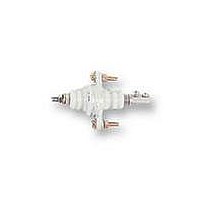
BF-1
Description
ELECTRODE HOLDER
Manufacturer
Omron
Datasheet
1.PFC-N8.pdf
(72 pages)
Specifications of BF-1
Description/function
General and industrial use electrode holder
Equipment Type
Electrode Holder
Lead Free Status / RoHS Status
Lead free / RoHS Compliant
Lead Free Status / RoHS Status
Lead free / RoHS Compliant


61F-Gj
61F-G1
Application 2: Automatic Water Supply Control with Abnormal Water Shortage Alarm
Note: Be sure to ground terminal E3.
Water supply
Pump OFF
Pump ON
B
Shortage
P
L
Water tank
E
1
E
2
E
4
E
3
200-VAC power supply
MCCB
THR
(U
(U
(U
2
2
1
indicator ON)
indicator OFF)
indicator OFF)
R S T
Electromagnetic
switch
M
61F-G1
P
Rated voltage:
S0--S1: 100 or 110 or 120 VAC
S0--S2: 200 or 220 or 240 VAC
100 V
200 V
S
0
Water supply source
S
0 V
1
U
*
2
S
Transformer
2
Tb
24 V
24 V
8 V
1
E
3
U
•
•
•
Ta
2
61F-11
Relay Unit
61F-11
Relay Unit
1
The pump stops (U2 indicator ON) when the water level reaches
E1 and starts (U2 indicator OFF) when the water level drops
below E2.
If the water level drops below E4 for any reason, the pump stops
(U1 indicator OFF) and the alarm sounds.
Insert a pushbutton switch (NO contact) between E3 and E4.
When starting the pump or after recovering from a power failure,
if the water level has not yet reached E4, press the pushbutton
switch to start the pump by short-circuiting E3 and E4. If the
pump stops upon releasing the pushbutton switch, keep
pressing the pushbutton switch.
E
2
E
U
1
U
Alarm
1
Tc
Water tank
U
U
1
2
1
2
E
2
’
B
Tb
2
E1
(E
4
’
)
E
3
E
4
E
2
E
1
Pushbutton
switch
PS-4S
61F-Gj
Related parts for BF-1
Image
Part Number
Description
Manufacturer
Datasheet
Request
R

Part Number:
Description:
G6S-2GLow Signal Relay
Manufacturer:
Omron Corporation
Datasheet:
Part Number:
Description:
Compact, Low-cost, SSR Switching 5 to 20 A
Manufacturer:
Omron Corporation
Datasheet:
Part Number:
Description:
Manufacturer:
Omron Corporation
Datasheet:
Part Number:
Description:
Manufacturer:
Omron Corporation
Datasheet:
Part Number:
Description:
Manufacturer:
Omron Corporation
Datasheet:
Part Number:
Description:
Manufacturer:
Omron Corporation
Datasheet:
Part Number:
Description:
Manufacturer:
Omron Corporation
Datasheet:
Part Number:
Description:
Manufacturer:
Omron Corporation
Datasheet: