BF-1 Omron, BF-1 Datasheet - Page 7
BF-1
Manufacturer Part Number
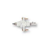
BF-1
Description
ELECTRODE HOLDER
Manufacturer
Omron
Datasheet
1.PFC-N8.pdf
(72 pages)
Specifications of BF-1
Description/function
General and industrial use electrode holder
Equipment Type
Electrode Holder
Lead Free Status / RoHS Status
Lead free / RoHS Compliant
Lead Free Status / RoHS Status
Lead free / RoHS Compliant


61F-Gj
Internal Circuit Diagrams
The schematic diagrams shown below typify the internal connections of the various 61F models. The designations Ta, Tb, and Tc (sometimes
referred to collectively as “U”) may occur more than once in a product, however, the “a” terminal is always an NO contact, a “b” terminal is an NC
contact, and the “c” terminal is the common terminal.
61F-G
61F-GH
(See note.)
100, 110
or 120 V
200, 220
or 240 V
100, 110
or 120 V
200, 220
or 240 V
Ta
Ta
0 V
0 V
S
S
0
0
Tc
Tc
U
U
S
S
1
1
24 V
24 V
8 V
24 V
Tb
Tb
61F-11
Relay Unit
61F-11H
Relay Unit
S
S
2
2
E
E
2
2
U
U
E
E
3
3
U
U
E
E
1
1
61F-GT
61F-GD
100, 110
or 120 V
200, 220
or 240 V
100, 110
or 120 V
200, 220
or 240 V
Ta
0 V
Ta
S
0 V
S
0
0
Tc
Tc
U
U
S
S
1
1
24 V
8 V
24 V
Tb
8 V
Tb
61F-11T
Relay Unit
S
61F-11D
Relay Unit
S
2
2
E
E
2
2
U
U
E
E
3
U
3
U
E
E
1
1
61F-GL
61F-GR
100, 110
or 120 V
200, 220
or 240 V
100, 110
or 120 V
200, 220
or 240 V
Ta
Ta
0 V
0 V
S
S
0
0
Tc
Tc
U
U
S
S
1
1
24 V
24 V
8 V
8 V
Tb
Tb
61F-11L
Relay Unit
S
61F-11R
Relay Unit
S
2
2
E
2
U
E
E
61F-Gj
3
3
U
U
E
E
1
1
U
Related parts for BF-1
Image
Part Number
Description
Manufacturer
Datasheet
Request
R

Part Number:
Description:
G6S-2GLow Signal Relay
Manufacturer:
Omron Corporation
Datasheet:
Part Number:
Description:
Compact, Low-cost, SSR Switching 5 to 20 A
Manufacturer:
Omron Corporation
Datasheet:
Part Number:
Description:
Manufacturer:
Omron Corporation
Datasheet:
Part Number:
Description:
Manufacturer:
Omron Corporation
Datasheet:
Part Number:
Description:
Manufacturer:
Omron Corporation
Datasheet:
Part Number:
Description:
Manufacturer:
Omron Corporation
Datasheet:
Part Number:
Description:
Manufacturer:
Omron Corporation
Datasheet:
Part Number:
Description:
Manufacturer:
Omron Corporation
Datasheet: