FGH30N60LSDTU Fairchild Semiconductor, FGH30N60LSDTU Datasheet
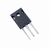
IGBT SWITCHING 600V 60A TO-247

FGH30N60LSDTU

Manufacturer Part Number
FGH30N60LSDTU
Description
IGBT SWITCHING 600V 60A TO-247
Manufacturer
Fairchild Semiconductor
Datasheet

Specifications of FGH30N60LSDTU

Voltage - Collector Emitter Breakdown (max)
600V
Vce(on) (max) @ Vge, Ic
1.4V @ 15V, 30A
Current - Collector (ic) (max)
60A
Power - Max
480W
Input Type
Standard
Mounting Type
Through Hole
Package / Case
TO-247-3
Channel Type
N
Configuration
Single
Collector-emitter Voltage
600V
Collector Current (dc) (max)
60A
Gate To Emitter Voltage (max)
±20V
Package Type
TO-247
Pin Count
3 +Tab
Mounting
Through Hole
Operating Temperature (min)
-55
Operating Temperature (max)
150C
Operating Temperature Classification
Military
Collector- Emitter Voltage Vceo Max
600 V
Maximum Gate Emitter Voltage
+/- 20 V
Maximum Operating Temperature
+ 150 C
Continuous Collector Current Ic Max
60 A
Minimum Operating Temperature
- 55 C
Mounting Style
Through Hole
Lead Free Status / RoHS Status
Lead free / RoHS Compliant
Igbt Type
-
Lead Free Status / Rohs Status
Compliant
©2006 Fairchild Semiconductor Corporation
FGH30N60LSD Rev. A2
FGH30N60LSD
Features
• Low saturation voltage: V
• High Input Impedance
• Low Conduction Loss
Applications
• Solar Inverters
• UPS, Welder
Absolute Maximum Ratings
Notes :
(1) Repetitive rating : Pulse width limited by max. junction temperature
Thermal Characteristics
V
V
I
I
I
P
T
T
T
R
R
R
C
CM (1)
FSM
stg
J
L
CES
GES
D
Symbol
θJC
θJC
θJA
Symbol
(IGBT)
(Diode)
Collector-Emitter Voltage
Gate-Emitter Voltage
Collector Current
Collector Current
Pulsed Collector Current
Non-repetitive Peak Surge Current
60Hz Single Half-Sine Wave
Maximum Power Dissipation
Operating Junction Temperature
Storage Temperature Range
Maximum Lead Temp. for soldering
Purposes, 1/8” from case for 5 seconds
Thermal Resistance, Junction-to-Case
Thermal Resistance, Junction-to-Ambient
CE(sat)
=1.1V @ I
E
COLLECTOR
Description
C
(FLANGE)
Parameter
G
C
= 30A
@ T
@ T
@ T
@ T
C
C
C
C
= 25°C
= 100°C
= 25°C
= 100°C
1
General Description
The FGH30N60LSD is a MOS gated high voltage switching
device combining the best features of MOSFETs and bipolar
transistors.This device has the high input impedance of a
MOSFET and the low on-state conduction loss of a bipolar
transistor.
FGH30N60LSD
Typ.
--
--
--
-55 to +150
-55 to +150
G
G
± 20
600
150
480
192
300
60
30
90
Max.
C
C
E
E
0.26
0.92
40
July 2008
www.fairchildsemi.com
Units
°C
°C
°C
Units
W
W
V
V
A
A
A
A
°C/W
°C/W
°C/W
tm

Related parts for FGH30N60LSDTU

FGH30N60LSDTU Summary of contents

Page 1

... R (Diode) Thermal Resistance, Junction-to-Case θJC R Thermal Resistance, Junction-to-Ambient θJA ©2006 Fairchild Semiconductor Corporation FGH30N60LSD Rev. A2 General Description = 30A The FGH30N60LSD is a MOS gated high voltage switching C device combining the best features of MOSFETs and bipolar transistors.This device has the high input impedance of a MOSFET and the low on-state conduction loss of a bipolar transistor ...

Page 2

... Package Marking and Ordering Information Device Marking Device FGH30N60LSD FGH30N60LSDTU Electrical Characteristics of the IGBT Symbol Parameter Off Characteristics BV Collector-Emitter Breakdown Voltage CES ∆B / Temperature Coefficient of Breakdown VCES ∆T Voltage J I Collector Cut-Off Current CES I G-E Leakage Current GES On Characteristics V G-E Threshold Voltage ...

Page 3

Electrical Characteristics of the Diode Parameter 15A 15A 600V =1A, di/dt = 100A/µ =15A, di/dt = 100A/µ ...

Page 4

Typical Performance Characteristics Figure 1.Typical Output Characteristics Collector-Emitter Voltage, V Figure 3. Typical Saturation Voltage Characteritics Collector-Emitter Voltage, V Figure 5. ...

Page 5

Typical Performance Characteristics Figure 7. Saturation Voltage vs. Vge 30A 60A 15A Gate-Emitter Voltage, V Figure 9. Gate Charge Characteristics 15 Common Emitter I = 30A C o ...

Page 6

Typical Performance Characteristics Figure 13. Turn-Off Characteristics vs. Gate Resistance 3000 1000 d(off) 100 Gate Resistance, R Figure 15. Turn-Off Characteristics vs. Collector Current 6000 t f 1000 t d(off) 100 ...

Page 7

Figure 19. Transient Thermal Impedance of IGBT 1 0.5 0.1 0.2 0.1 0.05 0.01 0.02 0.01 1E-3 1E-5 Figure 20. Typical Forward Voltage Drop 100 =125 = =25 ...

Page 8

Mechanical Dimensions TO-247AB (FKS PKG CODE 001) FGH30N60LSD Rev www.fairchildsemi.com ...

Page 9

... TRADEMARKS The following are registered and unregistered trademarks Fairchild Semiconductor owns or is authorized to use and is not intended exhaustive list of all such trademarks. ACEx™ FACT Quiet Series™ ActiveArray™ GlobalOptoisolator™ Bottomless™ GTO™ Build it Now™ HiSeC™ ...

Related keywords