IXST30N60B2D1 IXYS, IXST30N60B2D1 Datasheet - Page 2
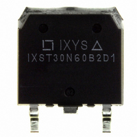
IXST30N60B2D1
Manufacturer Part Number
IXST30N60B2D1
Description
IGBT HS W/DIODE 600V 48A TO268
Manufacturer
IXYS
Datasheet
1.IXSH30N60B2D1.pdf
(6 pages)
Specifications of IXST30N60B2D1
Igbt Type
PT
Voltage - Collector Emitter Breakdown (max)
600V
Vce(on) (max) @ Vge, Ic
2.5V @ 15V, 24A
Current - Collector (ic) (max)
48A
Power - Max
250W
Input Type
Standard
Mounting Type
Surface Mount
Package / Case
TO-268
Channel Type
N
Configuration
Single
Collector-emitter Voltage
600V
Collector Current (dc) (max)
48A
Gate To Emitter Voltage (max)
±20V
Package Type
TO-268
Pin Count
3 +Tab
Mounting
Through Hole
Operating Temperature (min)
-55
Operating Temperature (max)
150C
Operating Temperature Classification
Military
Vces, (v)
600
Ic25, Tc=25°c, Igbt, (a)
48
Ic90, Tc=90°c, Igbt, (a)
-
Vce(sat), Max, Tj=25°c, Igbt, (v)
2.5
Tfi, Typ, Igbt, (ns)
140
Eoff, Typ, Tj=125°c, Igbt, (mj)
1.18
Rthjc, Max, Igbt, (k/w)
0.5
Package Style
TO-268
Lead Free Status / RoHS Status
Lead free / RoHS Compliant
Available stocks
Company
Part Number
Manufacturer
Quantity
Price
Company:

Part Number:
IXST30N60B2D1
Manufacturer:
IXYS
Quantity:
15 500


Note 1:
Symbol
g
C
C
C
Q
Q
Q
t
t
t
t
E
t
t
E
t
t
E
R
R
Reverse Diode (FRED)
Symbol
V
I
t
t
R
IXYS MOSFETs and IGBTs are covered by
one or moreof the following U.S. patents:
RM
d(on)
ri
d(off)
fi
d(on)
ri
d(off)
fi
rr
rr
fs
off
on
off
F
ies
oes
g
thJC
thCS
thJC
res
ge
gc
Pulse test, t ≤ 300 µs, duty cycle d ≤ 2 %
I
I
V
I
F
F
F
R
= 30A, V
= 50A, V
= 1 A; -di/dt = 100 A/µs; V
= 100 V
Inductive load, T
I
V
Switching times may increase for V
(Clamp) > 0.8 • V
increased R
Inductive load, T
I
V
Switching times may increase for
V
or increased R
Test Conditions
I
V
I
Test Conditions
C
C
f = 1 MHz
C
C
CE
CE
CE
CE
= 24A, V
= 24 A, V
= 24A; V
= 24A, V
= 400 V, R
= 400 V, R
(Clamp) > 0.8 • V
= 25 V, V
GE
GE
= 0 V
= 0 V, -di
GE
GE
GE
CE
G
GE
= 15 V
= 15 V, V
= 15 V
= 10 V, Note 1
G
G
G
= 0 V
4,835,592
4,850,072
4,881,106
= 5 Ω
= 5 Ω
CES
J
J
F
= 25° ° ° ° ° C
= 125° ° ° ° ° C
/dt = 100 A/µs
, higher T
CES
CE
R
, higher T
= 0.5 V
= 30 V
4,931,844
5,017,508
5,034,796
20N60B2D1
J
(T
(T
or
J
J
CES
= 25°C, unless otherwise specified)
= 25°C, unless otherwise specified)
J
5,049,961
5,063,307
5,187,117
CE
20N60B2D1
T
T
20N60B2
T
J
J
J
= 100°C
= 100°C 150
=150°C
5,237,481
5,381,025
5,486,715
min.
min.
7.0
Characteristic Values
Characteristic Values
1220
12.0
0.55
0.32
0.82
1.18
0.21
typ.
typ.
110
140
130
140
202
234
2.0
6,162,665
6,259,123 B1
6,306,728 B1
30
42
50
23
15
30
30
30
50
max.
0.50 K/W
280
300
1.6
2.5
2.5
0.9 K/W
1.0 mJ
max.
6,404,065 B1
6,534,343
6,583,505
K/W
nC
nC
nC
mJ
mJ
mJ
pF
pF
pF
pF
ns
ns
ns
ns
ns
ns
ns
ns
ns
ns
S
V
V
A
TO-247 (IXSH) Outline
TO-268 (IXST) Outline
6,683,344
6,710,405B2
6,710,463
Terminals: 1 - Gate
Dim.
A
A
A
b
b
b
C
D
E
e
L
L1
∅P
Q
1
2
1
2
IXSH 30N60B2D1
IXST 30N60B2D1
20.80
15.75
19.81
1.65
2.87
5.20
3.55
5.89
Min.
6,727,585
6,759,692
4.7
2.2
2.2
1.0
1
Millimeter
.4
2
3
21.46
16.26
20.32
Max.
2.54
2.13
3.12
5.72
4.50
3.65
6.40
5.3
2.6
1.4
.8
0.205 0.225
0.232 0.252
2 - Drain
.185
.087
.059
.040
.065
.113
.016
.819
.610
.780
.140
Min.
Inches
Max.
.209
.102
.098
.055
.084
.123
.031
.845
.640
.800
.177
.144
Related parts for IXST30N60B2D1
Image
Part Number
Description
Manufacturer
Datasheet
Request
R


Part Number:
Description:
HiPerFET Power MOSFETs
Manufacturer:
IXYS Corporation
Datasheet:
Part Number:
Description:
J-K-Type Flip-Flop
Manufacturer:
IXYS Corporation
Datasheet:
Part Number:
Description:
HiPerRF Power MOSFETs
Manufacturer:
IXYS Corporation
Datasheet:
Part Number:
Description:
Rectifier Module for Three Phase Power Factor Correction
Manufacturer:
IXYS Corporation
Datasheet:
Part Number:
Description:
Thyristor Modules Thyristor/Diode Modules
Manufacturer:
IXYS Corporation
Datasheet:
Part Number:
Description:
Thyristor Modules Thyristor/Diode Modules
Manufacturer:
IXYS Corporation
Datasheet:
Part Number:
Description:
Thyristor Modules Thyristor/Diode Modules
Manufacturer:
IXYS Corporation
Datasheet:
Part Number:
Description:
Thyristor Modules Thyristor/Diode Modules
Manufacturer:
IXYS Corporation
Datasheet:
Part Number:
Description:
Thyristor Modules /Diode Modules
Manufacturer:
IXYS Corporation
Datasheet:
Part Number:
Description:
Thyristor Modules /Diode Modules
Manufacturer:
IXYS Corporation
Datasheet:
Part Number:
Description:
Thyristor Modules Thyristor/Diode Modules
Manufacturer:
IXYS Corporation
Datasheet: