DMG1016V-7 Diodes Inc, DMG1016V-7 Datasheet

MOSFET N+P 20V 870MA SOT563

DMG1016V-7

Manufacturer Part Number
DMG1016V-7
Description
MOSFET N+P 20V 870MA SOT563
Manufacturer
Diodes Inc
Datasheet

Specifications of DMG1016V-7

Fet Type
N and P-Channel
Fet Feature
Logic Level Gate
Rds On (max) @ Id, Vgs
400 mOhm @ 600mA, 4.5V
Drain To Source Voltage (vdss)
20V
Current - Continuous Drain (id) @ 25° C
870mA, 640mA
Vgs(th) (max) @ Id
1V @ 250µA
Gate Charge (qg) @ Vgs
0.74nC @ 4.5V
Input Capacitance (ciss) @ Vds
60.67pF @ 16V
Power - Max
530mW
Mounting Type
Surface Mount
Package / Case
SOT-563
Transistor Polarity
N and P-Channel
Resistance Drain-source Rds (on)
0.5 Ohms, 1 Ohms
Drain-source Breakdown Voltage
20 V, - 20 V
Continuous Drain Current
870 mA, - 640 mA
Power Dissipation
530 mW
Maximum Operating Temperature
- 55 C
Mounting Style
SMD/SMT
Minimum Operating Temperature
+ 150 C
Lead Free Status / RoHS Status
Lead free / RoHS Compliant
Other names
DMG1016V-7DITR

Available stocks

Company
Part Number
Manufacturer
Quantity
Price
Part Number:
DMG1016V-7
Manufacturer:
TI
Quantity:
11 500
Part Number:
DMG1016V-7
Manufacturer:
DIODES
Quantity:
45 000
Part Number:
DMG1016V-7
Manufacturer:
DIODES
Quantity:
310
Part Number:
DMG1016V-7
Manufacturer:
DIODES/美台
Quantity:
20 000
Part Number:
DMG1016V-7
0
Company:
Part Number:
DMG1016V-7
Quantity:
1 083
Maximum Ratings N-CHANNEL – Q
Maximum Ratings P-CHANNEL – Q
Thermal Characteristics
Features
Drain Source Voltage
Gate-Source Voltage
Drain Current (Note 1)
Drain Source Voltage
Gate-Source Voltage
Drain Current (Note 1)
Power Dissipation (Note 1)
Thermal Resistance, Junction to Ambient (Note 1)
Operating and Storage Temperature Range
Notes:
DMG1016V
Document number: DS31767 Rev. 3 - 2
Low On-Resistance
Low Gate Threshold Voltage V
Low Input Capacitance
Fast Switching Speed
Low Input/Output Leakage
Complementary Pair MOSFET
Ultra-Small Surface Mount Package
Lead Free/RoHS Compliant (Note 2)
ESD Protected Gate to 2.5kV HBM
"Green" Device (Note 3)
Qualified to AEC-Q101 Standards for High Reliability
1. Device mounted on FR-4 PCB.
2. No purposefully added lead.
3. Diodes Inc.’s “Green” policy can be found on our website at http://www.diodes.com/products/lead_free/index.php.
ESD PROTECTED TO 2.5kV HBM
Characteristic
Characteristic
Characteristic
GS(th)
@T
<1V
A
= 25°C unless otherwise specified
TOP VIEW
2
1
T
T
T
T
@T
@T
A
A
A
A
= 25°C
= 85°C
= 25°C
= 85°C
A
A
= 25°C unless otherwise specified
www.diodes.com
= 25°C unless otherwise specified
COMPLEMENTARY PAIR ENHANCEMENT MODE MOSFET
SOT-563
1 of 8
BOTTOM VIEW
Mechanical Data
Symbol
Symbol
Symbol
T
J
V
V
V
V
Please click here to visit our online spice models database.
R
, T
P
GSS
GSS
DSS
I
DSS
I
Case: SOT-563
Case Material: Molded Plastic, “Green” Molding Compound.
UL Flammability Classification Rating 94V-0
Moisture Sensitivity: Level 1 per J-STD-020D
Terminal Connections: See Diagram
Terminals: Finish – Matte Tin annealed over Copper leadframe.
Solderable per MIL-STD-202, Method 208
Marking Information: See Page 7
Ordering Information: See Page 7
Weight: 0.006 grams (approximate)
θ JA
D
D
D
STG
Q
1
Internal Schematic
-55 to +150
D
S
1
1
TOP VIEW
Value
Value
Value
-640
-460
870
630
530
235
-20
20
±6
±6
G
G
2
1
S
D
2
2
Q
2
DMG1016V
© Diodes Incorporated
°C/W
Unit
Unit
Unit
mW
mA
mA
°C
V
V
V
V
May 2009

Related parts for DMG1016V-7

DMG1016V-7 Summary of contents

Page 1

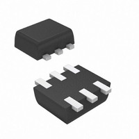
... GSS T = 25° 85° 25°C unless otherwise specified 2 A Symbol V DSS V GSS = 25° 85° 25°C unless otherwise specified A Symbol θ STG www.diodes.com DMG1016V TOP VIEW Internal Schematic Value Unit 20 V ±6 V 870 mA 630 Value Unit -20 V ±6 V -640 mA -460 Value Unit ...

Page 2

... Q g ⎯ ⎯ Q 100.3 gs ⎯ ⎯ 132 ⎯ ⎯ 5.1 t d(on) ⎯ ⎯ 8 ⎯ ⎯ 28.4 t d(off) ⎯ ⎯ www.diodes.com DMG1016V Unit Test Condition 0V 250μ 20V μ ±4.5V 250μ 4.5V 600mA GS D Ω 2.5V 500mA ...

Page 3

... DMG1016V T = 150° 125° 85° 25° -55°C A 0 GATE-SOURCE VOLTAGE (V) GS Fig. 2 Typical Transfer Characteristic T = 150° 125° 85° 25° -55° ...

Page 4

... Fig. 8 Diode Forward Voltage vs. Current 1,000 100 Fig. 10 Typical Leakage Current vs. Drain-Source Voltage D = 0.9 0.001 0.01 0 PULSE DURATION TIME (s) 1 Fig. 11 Transient Thermal Response www.diodes.com DMG1016V T = 25°C A 0.4 0.6 0.8 1.0 1 SOURCE-DRAIN VOLTAGE ( 150° 125° 85° 25° ...

Page 5

... Fig. 17 On-Resistance Variation with Temperature www.diodes.com DMG1016V 150° 85° 125° 25° -55°C A 0.5 1.0 1.5 2.0 2 GATE-SOURCE VOLTAGE (V) GS Fig. 13 Typical Transfer Characteristic ...

Page 6

... D = 0.9 0.001 0.01 0 PULSE DURATION TIME (s) 1 Fig. 22 Transient Thermal Response www.diodes.com DMG1016V T = 25°C A 0.4 0.6 0.8 1.0 1 SOURCE-DRAIN VOLTAGE (V) SD Fig. 19 Diode Forward Voltage vs. Current T = 150° 125° 85° 25° ...

Page 7

... Ordering Information (Note 5) Part Number DMG1016V-7 Notes: 5. For packaging details our website at http://www.diodes.com/datasheets/ap02007.pdf. Marking Information Date Code Key Year 2009 Code W Month Jan Feb Code 1 2 Package Outline Dimensions Suggested Pad Layout DMG1016V Document number: DS31767 Rev Case SOT-563 CA1 = Product Type Marking Code ...

Page 8

... Diodes Incorporated. Further, Customers must fully indemnify Diodes Incorporated and its representatives against any damages arising out of the use of Diodes Incorporated products in such safety-critical, life support devices or systems. Copyright © 2009, Diodes Incorporated www.diodes.com DMG1016V Document number: DS31767 Rev IMPORTANT NOTICE LIFE SUPPORT www.diodes.com DMG1016V May 2009 © Diodes Incorporated ...

Related keywords