SIA814DJ-T1-GE3 Vishay, SIA814DJ-T1-GE3 Datasheet - Page 2
SIA814DJ-T1-GE3
Manufacturer Part Number
SIA814DJ-T1-GE3
Description
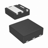
MOSFET N-CH 30V 4.5A SC70-6
Manufacturer
Vishay
Datasheet
1.SIA814DJ-T1-GE3.pdf
(10 pages)
Specifications of SIA814DJ-T1-GE3
Fet Type
MOSFET N-Channel, Metal Oxide
Fet Feature
Diode (Isolated)
Rds On (max) @ Id, Vgs
61 mOhm @ 3.3A, 10V
Drain To Source Voltage (vdss)
30V
Current - Continuous Drain (id) @ 25° C
4.5A
Vgs(th) (max) @ Id
1.5V @ 250µA
Gate Charge (qg) @ Vgs
11nC @ 10V
Input Capacitance (ciss) @ Vds
340pF @ 10V
Power - Max
6.5W
Mounting Type
Surface Mount
Package / Case
PowerPAK® SC-70-6 Dual
Transistor Polarity
N Channel + Schottky Diode
Continuous Drain Current Id
4.5A
Drain Source Voltage Vds
30V
On Resistance Rds(on)
110mohm
Rds(on) Test Voltage Vgs
12V
Lead Free Status / RoHS Status
Lead free / RoHS Compliant
Other names
SIA814DJ-T1-GE3TR
Available stocks
Company
Part Number
Manufacturer
Quantity
Price
Company:

Part Number:
SIA814DJ-T1-GE3
Manufacturer:
VISHAY
Quantity:
9 082


SiA814DJ
Vishay Siliconix
Notes:
a. Package limited.
b. Surface Mounted on 1" x 1" FR4 board.
c. t = 5 s.
d. See Solder Profile (
e. Rework Conditions: manual soldering with a soldering iron is not recommended for leadless components.
f. Maximum under Steady State conditions is 110 °C/W.
g. Maximum under Steady State conditions is 110 °C/W.
www.vishay.com
2
THERMAL RESISTANCE RATINGS
Parameter
Maximum Junction-to-Ambient (MOSFET)
Maximum Junction-to-Case (Drain) (MOSFET)
Maximum Junction-to-Ambient (Schottky)
Maximum Junction-to-Case (Drain) (Schottky)
SPECIFICATIONS T
Parameter
Static
Drain-Source Breakdown Voltage
V
V
Gate-Source Threshold Voltage
Gate-Source Leakage
Zero Gate Voltage Drain Current
On-State Drain Current
Drain-Source On-State Resistance
Forward Transconductance
Dynamic
Input Capacitance
Output Capacitance
Reverse Transfer Capacitance
Total Gate Charge
Gate-Source Charge
Gate-Drain Charge
Gate Resistance
Turn-On Delay Time
Rise Time
Turn-Off DelayTime
Fall Time
Turn-On Delay Time
Rise Time
Turn-Off DelayTime
Fall Time
copper (not plated) as a result of the singulation process in manufacturing. A solder fillet at the exposed copper tip cannot be guaranteed and
is not required to ensure adequate bottom side solder interconnection.
DS
GS(th)
Temperature Coefficient
Temperature Coefficient
b
h
ttp://www.vishay.com/ppg?73257). The PowerPAK SC-70 is a leadless package. The end of the lead terminal is exposed
a
a
J
= 25 °C, unless otherwise noted
a
b, g
b, f
ΔV
Symbol
ΔV
R
V
GS(th)
I
t
t
t
t
I
I
C
V
DS(on)
C
GS(th)
D(on)
C
Q
Q
d(on)
d(off)
d(on)
d(off)
GSS
DSS
DS
g
Q
R
t
t
DS
oss
t
t
iss
rss
gd
fs
gs
r
f
r
f
g
g
/T
/T
J
Steady State
Steady State
J
t ≤ 5 s
t ≤ 5 s
New Product
V
V
I
I
V
V
D
D
DS
DS
DS
DS
≅ 3.5 A, V
≅ 3.5 A, V
= 15 V, V
= 15 V, V
= 30 V, V
V
= 10 V, V
V
V
V
V
V
V
V
V
V
V
DS
DS
DD
DD
GS
DS
GS
GS
DS
GS
DS
Test Conditions
= 0 V, V
= V
= 0 V, I
= 15 V, R
= 15 V, R
= 30 V, V
= 4.5 V, I
= 2.5 V, I
≥ 5 V, V
= 15 V, I
= 10 V, I
I
D
f = 1 MHz
GEN
GEN
Symbol
GS
GS
= 250 µA
GS
GS
R
R
GS
R
R
, I
thJA
thJC
thJA
thJC
= 4.5 V, I
= 10 V, I
= 0 V, T
= 4.5 V, R
D
GS
D
= 0 V, f = 1 MHz
= 10 V, R
GS
D
D
= 250 µA
D
D
GS
L
L
= 250 µA
= ± 12 V
= 3.3 A
= 3.3 A
= 3.1 A
= 0.9 A
= 4.3 Ω
= 4.3 Ω
= 10 V
= 0 V
J
D
D
= 55 °C
= 4.3 A
g
g
= 4.3 A
= 1 Ω
= 1 Ω
Typical
12.5
52
62
15
Min.
0.6
30
15
Maximum
0.050
0.059
0.090
18.5
Typ.
- 3.7
340
3.2
0.9
0.8
65
16
76
27
45
25
10
10
15
10
12
15
10
9
7
2
5
S-81176-Rev. A, 26-May-08
Document Number: 68672
± 100
0.061
0.072
0.110
Max.
1.5
10
11
15
15
25
15
10
20
25
15
1
5
°C/W
Unit
mV/°C
Unit
nA
µA
pF
nC
ns
Ω
Ω
V
V
A
S
Related parts for SIA814DJ-T1-GE3
Image
Part Number
Description
Manufacturer
Datasheet
Request
R

Part Number:
Description:
N-channel 30-v D-s Mosfet With Trench Schottky Diode
Manufacturer:
Vishay
Datasheet:
Part Number:
Description:
357-036-542-201 CARDEDGE 36POS DL .156 BLK LOPRO
Manufacturer:
Vishay
Datasheet:
Part Number:
Description:
357-036-542-201 CARDEDGE 36POS DL .156 BLK LOPRO
Manufacturer:
Vishay
Datasheet:
Part Number:
Description:
357-036-542-201 CARDEDGE 36POS DL .156 BLK LOPRO
Manufacturer:
Vishay
Datasheet:
Part Number:
Description:
357-036-542-201 CARDEDGE 36POS DL .156 BLK LOPRO
Manufacturer:
Vishay
Datasheet:
Part Number:
Description:
357-036-542-201 CARDEDGE 36POS DL .156 BLK LOPRO
Manufacturer:
Vishay
Datasheet:
Part Number:
Description:
357-036-542-201 CARDEDGE 36POS DL .156 BLK LOPRO
Manufacturer:
Vishay
Datasheet:
Part Number:
Description:
357-036-542-201 CARDEDGE 36POS DL .156 BLK LOPRO
Manufacturer:
Vishay
Datasheet:
Part Number:
Description:
357-036-542-201 CARDEDGE 36POS DL .156 BLK LOPRO
Manufacturer:
Vishay
Datasheet:
Part Number:
Description:
357-036-542-201 CARDEDGE 36POS DL .156 BLK LOPRO
Manufacturer:
Vishay
Datasheet:
Part Number:
Description:
357-036-542-201 CARDEDGE 36POS DL .156 BLK LOPRO
Manufacturer:
Vishay
Datasheet:
Part Number:
Description:
357-036-542-201 CARDEDGE 36POS DL .156 BLK LOPRO
Manufacturer:
Vishay
Datasheet:
Part Number:
Description:
357-036-542-201 CARDEDGE 36POS DL .156 BLK LOPRO
Manufacturer:
Vishay
Datasheet:
Part Number:
Description:
357-036-542-201 CARDEDGE 36POS DL .156 BLK LOPRO
Manufacturer:
Vishay
Datasheet:
Part Number:
Description:
357-036-542-201 CARDEDGE 36POS DL .156 BLK LOPRO
Manufacturer:
Vishay
Datasheet: