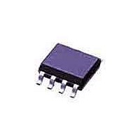
PCF8593TD NXP Semiconductors, PCF8593TD Datasheet - Page 23

PCF8593TD
Manufacturer Part Number
PCF8593TD
Description
Real Time Clock LO PWR CLOCK/CAL
Manufacturer
NXP Semiconductors
Datasheet
1.PCF8593P112.pdf
(35 pages)
Specifications of PCF8593TD
Function
Alarm, Timer Interrupt
Rtc Memory Size
8 B
Supply Voltage (max)
6 V
Supply Voltage (min)
1 V
Maximum Operating Temperature
+ 85 C
Minimum Operating Temperature
- 40 C
Mounting Style
SMD/SMT
Rtc Bus Interface
Serial
Package / Case
SOT-96
Time Format
HH:MM:SS:hh
Lead Free Status / RoHS Status
Lead free / RoHS Compliant
Other names
PCF8593T/1,112
NXP Semiconductors
11. Application information
PCF8593
Product data sheet
11.1.1 Method 1: Fixed OSCI capacitor
11.1.2 Method 2: OSCI trimmer
11.1.3 Method 3: Direct measurement
11.1 Oscillator frequency adjustment
By evaluating the average capacitance necessary for the application layout a fixed
capacitor can be used. The frequency is best measured via the 1 Hz signal which can be
programmed to occur at the interrupt output (pin 7). The frequency tolerance depends on
the quartz crystal tolerance, the capacitor tolerance and the device-to-device tolerance
(on average ±5 × 10
Using the alarm function (via the I
interrupt output for fast setting of a trimmer.
Procedure:
Routine:
Direct measurement of oscillator output (allowing for test probe capacitance).
•
•
•
•
Power the device on
Apply RESET.
Set clock to time t and set alarm to time t + Δt
at time t + Δt (interrupt) repeat routine.
All information provided in this document is subject to legal disclaimers.
−
6). Average deviations of ±5 minutes per year can be achieved.
Rev. 04 — 6 October 2010
2
C-bus) a signal faster than the 1 Hz is generated at the
Low power clock and calendar
PCF8593
© NXP B.V. 2010. All rights reserved.
23 of 35


