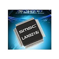
LAN9218I-MT SMSC, LAN9218I-MT Datasheet - Page 75

LAN9218I-MT
Manufacturer Part Number
LAN9218I-MT
Description
Ethernet ICs Indust Hi Perfrm Single-Chip
Manufacturer
SMSC
Type
Single Chip MAC and PHY Controllerr
Datasheet
1.LAN9218I-MT.pdf
(133 pages)
Specifications of LAN9218I-MT
Ethernet Connection Type
10 Base-T, 100 Base-TX
Minimum Operating Temperature
- 40 C
Mounting Style
SMD/SMT
Product
Ethernet Controllers
Number Of Transceivers
1
Standard Supported
802.3, 802.3u
Data Rate
10 Mbps, 100 Mbps
Supply Voltage (max)
3.3 V
Supply Voltage (min)
0 V
Supply Current (max)
69 mA
Maximum Operating Temperature
+ 85 C
Package / Case
TQFP-100
Lead Free Status / RoHS Status
Lead free / RoHS Compliant
Available stocks
Company
Part Number
Manufacturer
Quantity
Price
Company:
Part Number:
LAN9218I-MT
Manufacturer:
Standard
Quantity:
1 981
Company:
Part Number:
LAN9218I-MT
Manufacturer:
SMSC
Quantity:
6
Part Number:
LAN9218I-MT
Manufacturer:
SMSC
Quantity:
20 000
High-Performance Single-Chip 10/100 Ethernet Controller with HP Auto-MDIX and Industrial Temperature Support
Datasheet
SMSC LAN9218i
5.3.7
31:30
29-28
27-16
14-13
BITS
12-8
7-0
15
[31]
0
0
1
1
RX End Alignment. This field specifies the alignment that must be
maintained on the last data transfer of a buffer. The LAN9218i will add
extra DWORDs of data up to the alignment specified in the table below.
The host is responsible for removing these extra DWORDs. This
mechanism can be used to maintain cache line alignment on host
processors.
Please refer to
Note:
Reserved
RX DMA Count (RX_DMA_CNT). This 12-bit field indicates the amount
of data, in DWORDS, to be transferred out of the RX data FIFO before
asserting the RXD_INT. After being set, this field is decremented for each
DWORD of data that is read from the RX data FIFO. This field can be
overwritten with a new value before it reaches zero.
Force RX Discard (RX_DUMP). This self-clearing bit clears the RX data
and status FIFOs of all pending data. When a ‘1’ is written, the RX data
and status pointers are cleared to zero.
Note:
Reserved
RX Data Offset (RXDOFF). This field controls the offset value, in bytes,
that is added to the beginning of an RX data packet. The start of the valid
data will be shifted by the number of bytes specified in this field. An offset
of 0-31 bytes is a valid number of offset bytes.
Note:
Reserved
RX_CFG—Receive Configuration Register
This register controls the LAN9218i receive engine.
Offset:
The desired RX End Alignment must be set before reading a
packet. The RX end alignment can be changed between reading
receive packets, but must not be changed if the packet is
partially read.
Please refer to section “Force Receiver Discard (Receiver
Dump)” on page 53 for a detailed description regarding the use
of RX_DUMP.
The two LSBs of this field (D[9:8]) must not be modified while
the RX is running. The receiver must be halted, and all data
purged before these two bits can be modified. The upper three
bits (DWORD offset) may be modified while the receiver is
running. Modifications to the upper bits will take affect on the
next DWORD read.
[30]
0
1
0
1
Table 5.2
Table 5.2 RX Alignment Bit Definitions
for bit definitions
DESCRIPTION
6Ch
DATASHEET
75
Size:
16-byte alignment
32-byte alignment
4-byte alignment
End Alignment
Reserved
32 bits
TYPE
R/W
R/W
R/W
RO
SC
RO
RO
Revision 2.7 (03-15-10)
DEFAULT
00000
000h
00b
0
-
-
-


