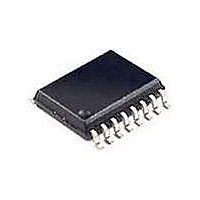
SI2400-BSR Silicon Laboratories Inc, SI2400-BSR Datasheet - Page 23

SI2400-BSR
Manufacturer Part Number
SI2400-BSR
Description
Telecom Line Management ICs CONTACT SILICON LABS FOR AVAILABILITY
Manufacturer
Silicon Laboratories Inc
Type
Integrated Global DAAr
Datasheet
1.SI2400-BS.pdf
(94 pages)
Specifications of SI2400-BSR
Product
Modem Chip
Supply Voltage (min)
3 V
Supply Current
21 mA
Maximum Operating Temperature
+ 85 C
Minimum Operating Temperature
- 40 C
Mounting Style
SMD/SMT
Package / Case
SOIC-16
Lead Free Status / RoHS Status
Lead free / RoHS Compliant
5.10. Tone Generation and Tone Detection
The Si2400 provides comprehensive and flexible tone
generation and detection. This includes all tones
needed to establish a circuit connection and to set up
and control a communication session. The tone
generation furnishes the DTMF tones for PSTN auto
dialing and the supervisory tones for call establishment.
The tone detection provides support for call progress
monitoring. The detector can also be user-programmed
to recognize up to four tones and two tone detection
bandpass filters.
DTMF tones may be detected and generated by using
the “ATA0” and “ATDT!0” commands described in the
AT command section. A description of the user-
programmable tones can be found in "7.1.DSP
Registers" on page 40.
The Si2400 DTMF decoder is designed for single loop
applications such as local detection of a parallel DTMF
device. Applications requiring DTMF detection across
two loops such as programming via a remote keypad
are not supported.
8-Bit Data
8-Bit Data
RXD
TXD
Start
Start
B0
B0
B1
D7
B1
D7
D8
B2
B2
Note: Baud rates (programmed through register SEO) can be set to the following: 228613, 245760 and 307200.
D8
D9
B3
High-Byte
High-Byte
D9
B3
D10
B4
D10
B4
D11
B5
D11
B5
D12
B6
PCM Transm it Tim ing
Figure 9. PCM Timing
PCM Receive Tim ing
D12
B6
B7
D13
D13
B7
Rev. 1.3
Stop
Stop
5.11. PCM Data Mode
The Si2400 has the ability to bypass the modem
algorithm and send 14-bit PCM data, sampled at
9600 Hz, across the DAA. To use this mode, it is
necessary to set the serial link (DTE) rate to at least
228613 bps SE0[2:0] (SD) = 101b, set S13[0] (PCM)
= 1
(Figure 9) requires that the high byte be sent first
containing bits D13–D7. The LSB (B0) must equal zero.
The low byte must be sent next containing bits D6–D0;
the LSB (B0) must equal one. The receive data format is
the same.
In PCM data mode, the line can be answered or
originated using the “ATDT#;” command. (The “;” is
used to keep the modem from leaving the command
mode.) When PCM data mode is enabled (set
S13[0] (PCM) = 1
(default)), data will immediately begin streaming into
and out of the serial port at a 9600 Hz 2 word rate. In
this mode, the controller will not detect dial tones or
other call progress tones. If desired, the user can
monitor these tones using manual call progress
detection prior to entering the PCM data mode.
To exit the PCM data mode, an escape must be
performed either by pulsing the ESC pin or by using 9-
bit data mode and setting the ninth bit. (TIES cannot be
used in PCM data mode.) The escape command will
disable PCM streaming, and the controller will again
accept AT style commands.
Start
b
, and set SE1[7:6] (MCKR) = 00
Start
B0
B0
D0
B1
D0
B1
b
D1
B2
Low-Byte
Low-Byte
B2
D1
D2
B3
and
D2
B3
B4
D3
D3
B4
D4
B5
SE4[5:4] (DRT) = 001
D4
B5
b
D5
. The data format
B6
Si2400
D5
B6
B7
D6
D6
B7
Stop
Stop
23
b


