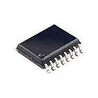
SI2400-BSR Silicon Laboratories Inc, SI2400-BSR Datasheet - Page 61

SI2400-BSR
Manufacturer Part Number
SI2400-BSR
Description
Telecom Line Management ICs CONTACT SILICON LABS FOR AVAILABILITY
Manufacturer
Silicon Laboratories Inc
Type
Integrated Global DAAr
Datasheet
1.SI2400-BS.pdf
(94 pages)
Specifications of SI2400-BSR
Product
Modem Chip
Supply Voltage (min)
3 V
Supply Current
21 mA
Maximum Operating Temperature
+ 85 C
Minimum Operating Temperature
- 40 C
Mounting Style
SMD/SMT
Package / Case
SOIC-16
Lead Free Status / RoHS Status
Lead free / RoHS Compliant
- Current page: 61 of 94
- Download datasheet (2Mb)
S62 (RC). Result Codes Override
Reset settings = 0000_0000
*Note: S62[3] (FLS), S62[2] (IR), S62[1] (NLR), and S62[0] (RR) only apply if S14[7] (MRCD) = 1.
Name
Type
Bit
Bit
7
6
5
4
3
2
1
0
CLD
R/W
D7
Name
WOR
OCR
CLD
NLR
LLC
FLS
RR
IR
OCR
R/W
D6
Carrier Loss Detector.
0 = Default.
1 = Caller ID sensitivity can be increased by 5 dB. When CLD = 1, the host is responsi-
ble for terminating caller ID reception by asserting an escape and issuing the ATH com-
mand.
Note: This bit also controls the carrier loss detection of non-caller ID modes of operation.
Overcurrent Result Code (“x”).
0 = Enable.
1 = Disable.
Low Loop Current (required for CTR21 operation).
This feature only works when SDF ≠ 0x00.
0 = Disable.
1 = Enable.
Wake-On-Ring Alert.
0 = Alert is not asserted upon a wake-on-ring event.
1 = Alert is asserted upon a wake-on-ring event SE2[7:6] (GPIO4) = 11
Hookswitch Flash Result Code (“f”).*
0 = Disable.
1 = Enable.
Intrusion Result Code (“I” and “i”).*
0 = Disable.
1 = Enable.
No Phone Line Result Code (“L” and “l”).*
0 = Disable.
1 = Enable.
Ring Result Code (“R”).*
0 = Disable.
1 = Enable.
b
(0x00)
R/W
LLC
D5
Therefore, the host must set CLD = 0 prior to answering a call via “ATA” or initiating a call
via “ATDT” or “ATDP”.
WOR
R/W
D4
R/W
FLS
D3
Rev. 1.3
R/W
D2
IR
Function
NLR
R/W
D1
R/W
RR
D0
b
.
Si2400
61
Related parts for SI2400-BSR
Image
Part Number
Description
Manufacturer
Datasheet
Request
R

Part Number:
Description:
IC ISOMODEM SYSTEM-SIDE 16SOIC
Manufacturer:
Silicon Laboratories Inc
Datasheet:

Part Number:
Description:
2400 BPS ISOMODEM EM SYSTEM-SIDE
Manufacturer:
Silicon Laboratories Inc
Datasheet:

Part Number:
Description:
IC ISOMODEM SYSTEM-SIDE 16SOIC
Manufacturer:
Silicon Laboratories Inc
Datasheet:

Part Number:
Description:
Telecom Line Management ICs 2400b/s System Side
Manufacturer:
Silicon Laboratories Inc
Datasheet:
Part Number:
Description:
SI2400 ISOMODEM LINE-SIDE
Manufacturer:
Silicon Laboratories Inc
Datasheet:
Part Number:
Description:
SMD/C°/SINGLE-ENDED OUTPUT SILICON OSCILLATOR
Manufacturer:
Silicon Laboratories Inc
Part Number:
Description:
Manufacturer:
Silicon Laboratories Inc
Datasheet:
Part Number:
Description:
N/A N/A/SI4010 AES KEYFOB DEMO WITH LCD RX
Manufacturer:
Silicon Laboratories Inc
Datasheet:
Part Number:
Description:
N/A N/A/SI4010 SIMPLIFIED KEY FOB DEMO WITH LED RX
Manufacturer:
Silicon Laboratories Inc
Datasheet:
Part Number:
Description:
N/A/-40 TO 85 OC/EZLINK MODULE; F930/4432 HIGH BAND (REV E/B1)
Manufacturer:
Silicon Laboratories Inc
Part Number:
Description:
EZLink Module; F930/4432 Low Band (rev e/B1)
Manufacturer:
Silicon Laboratories Inc
Part Number:
Description:
I°/4460 10 DBM RADIO TEST CARD 434 MHZ
Manufacturer:
Silicon Laboratories Inc
Part Number:
Description:
I°/4461 14 DBM RADIO TEST CARD 868 MHZ
Manufacturer:
Silicon Laboratories Inc


