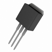
IRF740ALPBF Vishay, IRF740ALPBF Datasheet - Page 10

IRF740ALPBF
Manufacturer Part Number
IRF740ALPBF
Description
MOSFET N-CH 400V 10A TO-262
Manufacturer
Vishay
Specifications of IRF740ALPBF
Transistor Polarity
N-Channel
Fet Type
MOSFET N-Channel, Metal Oxide
Fet Feature
Standard
Rds On (max) @ Id, Vgs
550 mOhm @ 6A, 10V
Drain To Source Voltage (vdss)
400V
Current - Continuous Drain (id) @ 25° C
10A
Vgs(th) (max) @ Id
4V @ 250µA
Gate Charge (qg) @ Vgs
36nC @ 10V
Input Capacitance (ciss) @ Vds
1030pF @ 25V
Power - Max
3.1W
Mounting Type
Through Hole
Package / Case
I²Pak, TO-262 (3 straight leads + tab)
Minimum Operating Temperature
- 55 C
Configuration
Single
Resistance Drain-source Rds (on)
0.55 Ohm @ 10 V
Drain-source Breakdown Voltage
400 V
Gate-source Breakdown Voltage
+/- 30 V
Continuous Drain Current
10 A
Power Dissipation
3100 mW
Maximum Operating Temperature
+ 150 C
Mounting Style
Through Hole
Continuous Drain Current Id
10A
Drain Source Voltage Vds
400V
On Resistance Rds(on)
550mohm
Rds(on) Test Voltage Vgs
10V
Threshold Voltage Vgs Typ
4V
Lead Free Status / RoHS Status
Lead free / RoHS Compliant
Lead Free Status / RoHS Status
Lead free / RoHS Compliant, Lead free / RoHS Compliant
Other names
*IRF740ALPBF
Available stocks
Company
Part Number
Manufacturer
Quantity
Price
Part Number:
IRF740ALPBF
Manufacturer:
VISHAY/威世
Quantity:
20 000
‚
ƒ
Document Number: 91052
Notes:
D
IR WORLD HEADQUARTERS: 233 Kansas St., El Segundo, California 90245, USA Tel: (310) 252-7105
For recommended footprint and soldering techniques refer to application note #AN-994.
When mounted on 1" square PCB ( FR-4 or G-10 Material ).
Repetitive rating; pulse width limited by
I
R
max. junction temperature. ( See fig. 11 )
T
2
Starting T
SD
J
Pak Tape & Reel Infomation
G
≤ 150°C
≤ 10A, di/dt ≤ 330A/µs, V
= 25Ω, I
J
= 25°C, L = 12.6mH
AS
= 10A. (See Figure 12)
DD
≤ V
FEED DIRECTION
FEED DIRECTION
NOTES :
1. COMFORMS TO EIA-418.
2. CONTROLLING DIMENSION: MILLIMETER.
3. DIMENSION MEASURED @ HUB.
4. INCLUDES FLANGE DISTORTION @ OUTER EDGE.
(BR)DSS
TRR
TRL
330.00
(14.173)
,
MAX.
1.85 (.073)
1.65 (.065)
10.90 (.429)
10.70 (.421)
13.50 (.532)
12.80 (.504)
„
…
†
Pulse width ≤ 300µs; duty cycle ≤ 2%.
C
Uses IRF740A data and test conditions
as C
4.10 (.161)
3.90 (.153)
oss
Data and specifications subject to change without notice.
1.60 (.063)
1.50 (.059)
eff. is a fixed capacitance that gives the same charging time
oss
while V
16.10 (.634)
15.90 (.626)
DS
11.60 (.457)
11.40 (.449)
1.75 (.069)
1.25 (.049)
is rising from 0 to 80% V
1.60 (.063)
1.50 (.059)
27.40 (1.079)
23.90 (.941)
26.40 (1.039)
24.40 (.961)
15.42 (.609)
15.22 (.601)
4
3
30.40 (1.197)
0.368 (.0145)
0.342 (.0135)
60.00 (2.362)
MAX.
24.30 (.957)
23.90 (.941)
4.72 (.136)
4.52 (.178)
4
MIN.
TAC Fax: (310) 252-7903
DSS
www.vishay.com
07/04
10


