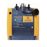
DTX-MFM2 FLUKE NETWORKS, DTX-MFM2 Datasheet - Page 22

DTX-MFM2
Manufacturer Part Number
DTX-MFM2
Description
DTX-MFM2 REPLACEMENT FOR DTX-MFM
Manufacturer
FLUKE NETWORKS
Datasheet
1.DTX-MFM2.pdf
(74 pages)
Specifications of DTX-MFM2
Multimode Fiber Module Set
ROHS COMPLIANT
DTX-MFM2/GFM2/SFM2 Fiber Modules
Users Manual
16
SETUP > Fiber Loss >
Bi-Directional
SETUP > Fiber Loss >
Number of Adapters
SETUP > Fiber Loss >
Number of Splices
SETUP > Fiber Loss >
Connector Type
Setting
When enabled in Smart Remote or Loopback mode, the tester prompts you to swap the test
connections halfway through the test. The tester can then make bi-directional measurements
for each fiber at each wavelength (850 nm/1300 nm, 850 nm/1310 nm, or 1310 nm/1550 nm).
If the selected limit uses a calculated loss limit, enter the number of adapters and splices that
will be added to the fiber path after the reference is set. Figure 6 shows an example of how to
determine the Number of Adapters setting.
Only limits that use maximum values for loss per km, loss per connector, and loss per splice use a
calculated limit for overall loss. For example, limits for fiber backbones use a calculated loss
limit.
Select the type of connector used in the cabling. This setting affects only the diagrams shown
for reference connections. If the cabling's connector type is not listed, use General.
Table 2. Fiber Test Settings (cont.)
Description
-continued-


