IRF840ASTRLPBF Vishay, IRF840ASTRLPBF Datasheet - Page 10
IRF840ASTRLPBF
Manufacturer Part Number
IRF840ASTRLPBF
Description
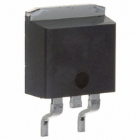
MOSFET N-CH 500V 8A D2PAK
Manufacturer
Vishay
Datasheet
1.IRF840ASPBF.pdf
(11 pages)
Specifications of IRF840ASTRLPBF
Transistor Polarity
N-Channel
Fet Type
MOSFET N-Channel, Metal Oxide
Fet Feature
Standard
Rds On (max) @ Id, Vgs
850 mOhm @ 4.8A, 10V
Drain To Source Voltage (vdss)
500V
Current - Continuous Drain (id) @ 25° C
8A
Vgs(th) (max) @ Id
4V @ 250µA
Gate Charge (qg) @ Vgs
38nC @ 10V
Input Capacitance (ciss) @ Vds
1018pF @ 25V
Power - Max
3.1W
Mounting Type
Surface Mount
Package / Case
D²Pak, TO-263 (2 leads + tab)
Minimum Operating Temperature
- 55 C
Configuration
Single
Resistance Drain-source Rds (on)
0.85 Ohm @ 10 V
Drain-source Breakdown Voltage
500 V
Gate-source Breakdown Voltage
+/- 30 V
Continuous Drain Current
8 A
Power Dissipation
3100 mW
Maximum Operating Temperature
+ 150 C
Mounting Style
SMD/SMT
Continuous Drain Current Id
8A
Drain Source Voltage Vds
500V
On Resistance Rds(on)
850mohm
Rds(on) Test Voltage Vgs
10V
Leaded Process Compatible
Yes
Lead Free Status / RoHS Status
Lead free / RoHS Compliant
Lead Free Status / RoHS Status
Lead free / RoHS Compliant, Lead free / RoHS Compliant
Available stocks
Company
Part Number
Manufacturer
Quantity
Price


IRF840AS/LPbF
Document Number: 91066
* When mounted on 1" square PCB ( FR-4 or G-10 Material ).
IR WORLD HEADQUARTERS: 233 Kansas St., El Segundo, California 90245, USA Tel: (310) 252-7105
D
‚
ƒ
Notes:
For recommended footprint and soldering techniques refer to application note #AN-994.
2
Repetitive rating; pulse width limited by
I
max. junction temperature. (See fig. 11)
R
T
Starting T
SD
Pak Tape & Reel Infor-
J
G
≤ 150°C
≤ 8.0A, di/dt ≤ 100A/µs, V
= 25Ω, I
J
= 25°C, L = 16mH
AS
F E E D D IR E C T I O N
= 8.0A. (See Figure 12)
F E E D D I R E C T IO N
N O T E S :
1 . C O M F O R M S T O E IA -4 1 8.
2 . C O N T R O LL IN G D IM E N S IO N : M IL L IM E T E R .
3 . D IM E N S IO N M E A S U R E D @ H U B .
4 . IN C L U D E S F LA N G E D IS T O R T IO N @ O U T E R E D G E .
T R R
T R L
330.00
(14.173)
M A X.
DD
1 .8 5 (.07 3 )
1 .6 5 (.06 5 )
≤ V
1 0 . 9 0 (.4 2 9 )
1 0 . 7 0 (.4 2 1 )
1 3 .5 0 (.5 3 2)
1 2 .8 0 (.5 0 4)
(BR)DSS
4 .10 (.1 6 1)
3 .90 (.1 5 3)
,
1 .6 0 (.06 3 )
1 .5 0 (.05 9 )
„
…
†
Data and specifications subject to change without notice.
Pulse width ≤ 300µs; duty cycle ≤ 2%.
C
Uses IRF840A data and test conditions
as C
oss
eff. is a fixed capacitance that gives the same charging time
oss
1 6 .1 0 (.6 3 4 )
1 5 .9 0 (.6 2 6 )
while V
1 1 .6 0 (.4 5 7 )
1 1 .4 0 (.4 4 9 )
1 .7 5 (.0 6 9 )
1 .2 5 (.0 4 9 )
1 .6 0 (.0 6 3 )
1 .5 0 (.0 5 9 )
DS
2 7 .40 (1 .0 79 )
2 3 .90 (.9 4 1)
26.40 (1.039)
24.40 (.961)
is rising from 0 to 80% V
1 5 .4 2 (.6 0 9 )
1 5 .2 2 (.6 0 1 )
4
3
3 0.4 0 (1 .1 97 )
0 .3 6 8 (.0 1 4 5 )
0 .3 4 2 (.0 1 3 5 )
6 0 .00 (2 .3 6 2)
M A X .
2 4 .3 0 ( .9 5 7 )
2 3 .9 0 ( .9 4 1 )
4 .7 2 (.1 3 6 )
4 .5 2 (.1 7 8 )
4
M IN .
TAC Fax: (310) 252-7903
DSS
www.vishay.com
04/04
10
Related parts for IRF840ASTRLPBF
Image
Part Number
Description
Manufacturer
Datasheet
Request
R

Part Number:
Description:
MOSFET N-CH 500V 8A D2PAK
Manufacturer:
Vishay
Datasheet:

Part Number:
Description:
MOSFET N-CH 500V 8A TO-220AB
Manufacturer:
Vishay
Datasheet:

Part Number:
Description:
357-036-542-201 CARDEDGE 36POS DL .156 BLK LOPRO
Manufacturer:
Vishay
Datasheet:
Part Number:
Description:
357-036-542-201 CARDEDGE 36POS DL .156 BLK LOPRO
Manufacturer:
Vishay
Datasheet:
Part Number:
Description:
357-036-542-201 CARDEDGE 36POS DL .156 BLK LOPRO
Manufacturer:
Vishay
Datasheet:
Part Number:
Description:
357-036-542-201 CARDEDGE 36POS DL .156 BLK LOPRO
Manufacturer:
Vishay
Datasheet:
Part Number:
Description:
357-036-542-201 CARDEDGE 36POS DL .156 BLK LOPRO
Manufacturer:
Vishay
Datasheet:
Part Number:
Description:
357-036-542-201 CARDEDGE 36POS DL .156 BLK LOPRO
Manufacturer:
Vishay
Datasheet:
Part Number:
Description:
357-036-542-201 CARDEDGE 36POS DL .156 BLK LOPRO
Manufacturer:
Vishay
Datasheet:
Part Number:
Description:
357-036-542-201 CARDEDGE 36POS DL .156 BLK LOPRO
Manufacturer:
Vishay
Datasheet:
Part Number:
Description:
357-036-542-201 CARDEDGE 36POS DL .156 BLK LOPRO
Manufacturer:
Vishay
Datasheet:
Part Number:
Description:
357-036-542-201 CARDEDGE 36POS DL .156 BLK LOPRO
Manufacturer:
Vishay
Datasheet:
Part Number:
Description:
357-036-542-201 CARDEDGE 36POS DL .156 BLK LOPRO
Manufacturer:
Vishay
Datasheet:
Part Number:
Description:
357-036-542-201 CARDEDGE 36POS DL .156 BLK LOPRO
Manufacturer:
Vishay
Datasheet:
Part Number:
Description:
357-036-542-201 CARDEDGE 36POS DL .156 BLK LOPRO
Manufacturer:
Vishay
Datasheet: