STP4N150 STMicroelectronics, STP4N150 Datasheet - Page 9
STP4N150
Manufacturer Part Number
STP4N150
Description
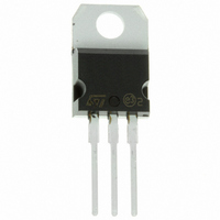
MOSFET N-CH 1500V 4A TO-220
Manufacturer
STMicroelectronics
Series
PowerMESH™r
Specifications of STP4N150
Fet Type
MOSFET N-Channel, Metal Oxide
Fet Feature
Standard
Rds On (max) @ Id, Vgs
7 Ohm @ 2A, 10V
Drain To Source Voltage (vdss)
1500V (1.5kV)
Current - Continuous Drain (id) @ 25° C
4A
Vgs(th) (max) @ Id
5V @ 250µA
Gate Charge (qg) @ Vgs
50nC @ 10V
Input Capacitance (ciss) @ Vds
1300pF @ 25V
Power - Max
160W
Mounting Type
Through Hole
Package / Case
TO-220-3 (Straight Leads)
Configuration
Single
Transistor Polarity
N-Channel
Resistance Drain-source Rds (on)
7 Ohm @ 10 V
Forward Transconductance Gfs (max / Min)
3.5 S
Drain-source Breakdown Voltage
1500 V
Gate-source Breakdown Voltage
+/- 30 V
Continuous Drain Current
4 A
Power Dissipation
160000 mW
Maximum Operating Temperature
+ 150 C
Mounting Style
Through Hole
Minimum Operating Temperature
- 55 C
Continuous Drain Current Id
4A
Drain Source Voltage Vds
1.5kV
On Resistance Rds(on)
7ohm
Rds(on) Test Voltage Vgs
30V
Threshold Voltage Vgs Typ
4V
Rohs Compliant
Yes
Lead Free Status / RoHS Status
Lead free / RoHS Compliant
Other names
497-5091-5
Available stocks
Company
Part Number
Manufacturer
Quantity
Price
Company:

Part Number:
STP4N150
Manufacturer:
FSC
Quantity:
3 000
Part Number:
STP4N150
Manufacturer:
ST
Quantity:
20 000


STFW4N150, STP4N150, STW4N150
3
Figure 19. Switching times test circuit for
Figure 21. Test circuit for inductive load
Figure 23. Unclamped inductive waveform
25 Ω
P
V
W
DD
G
V
D
S
GS
D.U.T.
A
B
Test circuits
resistive load
switching and diode recovery times
I
D
V
R
D
G
R
G
FAST
DIODE
B
A
I
DM
V
G
A
B
D
R
D.U.T.
L
S
D
L=100µH
V
2200
µF
(BR)DSS
3.3
µF
3.3
µF
Doc ID 11262 Rev 9
1000
µF
AM01468v1
AM01472v1
AM01470v1
V
DD
V
DD
V
DD
Figure 20. Gate charge test circuit
Figure 22. Unclamped inductive load test
Figure 24. Switching time waveform
V
P
i
V
W
0
0
i
=20V=V
P
w
10%
2200
µF
1kΩ
GMAX
td
circuit
on
I
90%
V
t
D
on
D
I
G
2.7kΩ
12V
t
=CONST
r
47kΩ
10%
V
GS
L
D.U.T.
V
47kΩ
100Ω
DS
2200
µF
100nF
90%
td
off
t
off
Test circuits
3.3
µF
D.U.T.
t
f
10%
AM01469v1
AM01471v1
AM01473v1
1kΩ
90%
V
V
V
9/15
G
DD
DD
Related parts for STP4N150
Image
Part Number
Description
Manufacturer
Datasheet
Request
R

Part Number:
Description:
STMicroelectronics [RIPPLE-CARRY BINARY COUNTER/DIVIDERS]
Manufacturer:
STMicroelectronics
Datasheet:
Part Number:
Description:
STMicroelectronics [LIQUID-CRYSTAL DISPLAY DRIVERS]
Manufacturer:
STMicroelectronics
Datasheet:

Part Number:
Description:
BOARD EVAL FOR MEMS SENSORS
Manufacturer:
STMicroelectronics
Datasheet:
Part Number:
Description:
NPN TRANSISTOR POWER MODULE
Manufacturer:
STMicroelectronics
Datasheet:
Part Number:
Description:
TURBOSWITCH ULTRA-FAST HIGH VOLTAGE DIODE
Manufacturer:
STMicroelectronics
Datasheet:
Part Number:
Description:
Manufacturer:
STMicroelectronics
Datasheet:
Part Number:
Description:
DIODE / SCR MODULE
Manufacturer:
STMicroelectronics
Datasheet:
Part Number:
Description:
DIODE / SCR MODULE
Manufacturer:
STMicroelectronics
Datasheet:
Part Number:
Description:
Search -----> STE16N100
Manufacturer:
STMicroelectronics
Datasheet:
Part Number:
Description:
Search ---> STE53NA50
Manufacturer:
STMicroelectronics
Datasheet:
Part Number:
Description:
NPN Transistor Power Module
Manufacturer:
STMicroelectronics
Datasheet:
Part Number:
Description:
DIODE / SCR MODULE
Manufacturer:
STMicroelectronics
Datasheet: