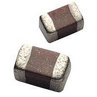
12065E104ZAT2A AVX Corporation, 12065E104ZAT2A Datasheet - Page 31

12065E104ZAT2A
Manufacturer Part Number
12065E104ZAT2A
Description
Cap Ceramic 0.1uF 50VDC Z5U -20% to 80% SMD 1206 Paper T/R
Manufacturer
AVX Corporation
Type
Flatr
Series
1206r
Specifications of 12065E104ZAT2A
Package/case
1206
Mounting
Surface Mount
Capacitance Value
0.1 uF
Dielectric
Z5U
Voltage
50 Vdc
Product Length
3.2 mm
Product Height
1.5(Max) mm
Product Depth
1.6 mm
Tolerance
-20 to 80 %
Dielectric Characteristic
Z5U
Capacitance
0.1µF
Capacitance Tolerance
+80, -20%
Voltage Rating
50VDC
Capacitor Case Style
1206
No. Of Pins
2
Capacitor Mounting
SMD
Rohs Compliant
Yes
Case Code
1206
Case Size
1206
Material, Element
Ceramic
Termination
SMT
Operating Temperature Range
+ 10 C to + 85 C
Temperature Coefficient / Code
Z5U
Package / Case
1206 (3216 metric)
Product
General Type MLCCs
Dimensions
1.6 mm (0.063 in) W x 3.2 mm (0.126 in) L
Dissipation Factor Df
4
Termination Style
SMD/SMT
Lead Free Status / Rohs Status
RoHS Compliant part
30
MIL-PRF-55681/Chips
Military Part Number Identification
CDR31 thru CDR35
CROSS REFERENCE: AVX/MIL-PRF-55681/CDR31 THRU CDR35
MIL Style: CDR31, CDR32, CDR33, CDR34, CDR35
Voltage Temperature Limits:
BP = 0 ± 30 ppm/°C without voltage; 0 ± 30 ppm/°C with
BX = ± 15% without voltage; +15 –25% with rated voltage
Capacitance: Two digit figures followed by multiplier
(number of zeros to be added) e.g., 101 = 100 pF
Rated Voltage: A = 50V, B = 100V
Capacitance Tolerance: C ±.25 pF, D ±.5 pF, F ±1%
Per MIL-PRF-55681
T
(Metric Sizes)
from -55°C to +125°C
rated voltage from -55°C to +125°C
CDR31
CDR32
CDR33
CDR34
CDR35
W
Style
0805
1206
1210
1812
1825
AVX
J ±5%, K ±10%, M ±20%
Length (L)
D
L
(mm)
2.00
3.20
3.20
4.50
4.50
t
Width (W)
(mm)
1.25
1.60
2.50
3.20
6.40
MILITARY DESIGNATION PER MIL-PRF-55681
Part Number Example
(example)
MIL Style
Voltage-temperature
Limits
Capacitance
Rated Voltage
Capacitance Tolerance
Termination Finish
Failure Rate
Thickness (T)
Termination Finish:
M = Palladium Silver
N = Silver Nickel Gold
S = Solder-coated
*Solder shall have a melting point of 200°C or less.
Failure Rate Level: M = 1.0%, P = .1%, R = .01%,
Packaging: Bulk is standard packaging. Tape and reel
per RS481 is available upon request.
Max. (mm)
1.3
1.3
1.5
1.5
1.5
CDR31
Min. (mm)
BP
.50
—
—
—
—
S = .001%
D
101
U = Base Metallization/Barrier
W = Base Metallization/Barrier
Metal/Solder Coated*
Metal/Tinned (Tin or Tin/
Lead Alloy)
Max. (mm)
B
Termination Band (t)
.70
.70
.70
.70
.70
K
S
Min. (mm)
M
.30
.30
.30
.30
.30


