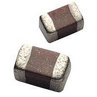
12065E104ZAT2A AVX Corporation, 12065E104ZAT2A Datasheet - Page 9

12065E104ZAT2A
Manufacturer Part Number
12065E104ZAT2A
Description
Cap Ceramic 0.1uF 50VDC Z5U -20% to 80% SMD 1206 Paper T/R
Manufacturer
AVX Corporation
Type
Flatr
Series
1206r
Specifications of 12065E104ZAT2A
Package/case
1206
Mounting
Surface Mount
Capacitance Value
0.1 uF
Dielectric
Z5U
Voltage
50 Vdc
Product Length
3.2 mm
Product Height
1.5(Max) mm
Product Depth
1.6 mm
Tolerance
-20 to 80 %
Dielectric Characteristic
Z5U
Capacitance
0.1µF
Capacitance Tolerance
+80, -20%
Voltage Rating
50VDC
Capacitor Case Style
1206
No. Of Pins
2
Capacitor Mounting
SMD
Rohs Compliant
Yes
Case Code
1206
Case Size
1206
Material, Element
Ceramic
Termination
SMT
Operating Temperature Range
+ 10 C to + 85 C
Temperature Coefficient / Code
Z5U
Package / Case
1206 (3216 metric)
Product
General Type MLCCs
Dimensions
1.6 mm (0.063 in) W x 3.2 mm (0.126 in) L
Dissipation Factor Df
4
Termination Style
SMD/SMT
Lead Free Status / Rohs Status
RoHS Compliant part
C0G (NP0) Capacitors for RF/Microwave
Ultra Low ESR, “U” Series, C0G (NP0) Chip Capacitors
GENERAL INFORMATION
“U” Series capacitors are C0G (NP0) chip capacitors spe-
cially designed for “Ultra” low ESR for applications in the
communications market. Max ESR and effective capacitance
HOW TO ORDER
DIMENSIONS:
ELECTRICAL CHARACTERISTICS
Capacitance Values and Tolerances:
Temperature Coefficient of Capacitance (TC):
Insulation Resistance (IR):
Working Voltage (WVDC):
8
Case Size
B
0805
Size
0402
0603
0805
1210
0402
0603
0805
1210
Size 0402 - 0.2 pF to 15 pF @ 1 MHz
Size 0603 - 1.0 pF to 47 pF @ 1 MHz
Size 0805 - 1.6 pF to 160 pF @ 1 MHz
Size 1210 - 2.4 pF to 1000 pF @ 1 MHz
0 ± 30 ppm/°C (-55° to +125°C)
10
10
Size
0402 -
0603 -
0805 -
1210 -
A
0402
12
11
Ω min. @ 25°C and rated WVDC
Ω min. @ 125°C and rated WVDC
0.039 ± 0.004 (1.00 ± 0.10) 0.020 ± 0.004 (0.50 ± 0.10)
0.060 ± 0.010 (1.52 ± 0.25) 0.030 ± 0.010 (0.76 ± 0.25)
0.079 ± 0.008 (2.01 ± 0.20) 0.049 ± 0.008 (1.25 ± 0.20) 0.040 ± 0.005 (1.02 ± 0.127) 0.020 ± 0.010 (0.51 ± 0.255)
0.126 ± 0.008 (3.2 ± 0.20)
C
Working Voltage
25 WVDC
200, 100, 50 WVDC
200, 100 WVDC
200, 100 WVDC
Voltage
3 = 25V
5 = 50V
1 = 100V
2 = 200V
Code
1
inches (millimeters)
A
Dielectric =
Ultra Low
B
D
ESR
U
EIA Capacitance Code in pF.
First two digits = significant figures
or “R” for decimal place.
Third digit = number of zeros or after
“R” significant figures.
0.098 ± 0.008 (2.49 ± 0.20) 0.050 ± 0.005 (1.27 ± 0.127) 0.025 ± 0.015 (0.635 ± 0.381) 0.040 (1.02) min.
E
A
0603
D
Capacitance
C
B
100
Capacitance
M = ±20%
Tolerance
C = ±0.25 pF
D = ±0.5 pF
G = ±2%
B = ±0.1 pF
K = ±10%
F = ±1%
J = ±5%
Code
B
J
D
0.024 (0.60) max.
0.036 (0.91) max.
are met on each value producing lot to lot uniformity.
Sizes available are EIA chip sizes 0603, 0805, and 1210.
Dielectric Working Voltage (DWV):
Equivalent Series Resistance Typical (ESR):
Marking:
MILITARY SPECIFICATIONS
A
E
0805
D
C
Failure Rate
250% of rated WVDC
0402 -
0603 -
0805 -
1210 -
Meets or exceeds the requirements of MIL-C-55681
Applicable
C
A = Not
Code
A
Laser marking EIA J marking standard
(except 0603) (capacitance code and
tolerance upon request).
See Performance Curve, page 9
See Performance Curve, page 9
See Performance Curve, page 9
See Performance Curve, page 9
0.010 ± 0.005 (0.25 ± 0.13)
Termination
T= Plated Ni
and Solder
T
B
N/A
D
D
Packaging
2 = 7" Reel
4 = 13" Reel
9 = Bulk
A
E
Code
1210
2
D
C
0.030 (0.76) min.
0.020 (0.51) min.
inches (mm)
A = Standard
N/A
Special
E
Code
A


