12065E104ZAT2A AVX Corporation, 12065E104ZAT2A Datasheet - Page 5
12065E104ZAT2A
Manufacturer Part Number
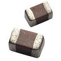
12065E104ZAT2A
Description
Cap Ceramic 0.1uF 50VDC Z5U -20% to 80% SMD 1206 Paper T/R
Manufacturer
AVX Corporation
Type
Flatr
Series
1206r
Specifications of 12065E104ZAT2A
Package/case
1206
Mounting
Surface Mount
Capacitance Value
0.1 uF
Dielectric
Z5U
Voltage
50 Vdc
Product Length
3.2 mm
Product Height
1.5(Max) mm
Product Depth
1.6 mm
Tolerance
-20 to 80 %
Dielectric Characteristic
Z5U
Capacitance
0.1µF
Capacitance Tolerance
+80, -20%
Voltage Rating
50VDC
Capacitor Case Style
1206
No. Of Pins
2
Capacitor Mounting
SMD
Rohs Compliant
Yes
Case Code
1206
Case Size
1206
Material, Element
Ceramic
Termination
SMT
Operating Temperature Range
+ 10 C to + 85 C
Temperature Coefficient / Code
Z5U
Package / Case
1206 (3216 metric)
Product
General Type MLCCs
Dimensions
1.6 mm (0.063 in) W x 3.2 mm (0.126 in) L
Dissipation Factor Df
4
Termination Style
SMD/SMT
Lead Free Status / Rohs Status
RoHS Compliant part


C0G (NP0) Dielectric
General Specifications
PART NUMBER (see page 3 for complete part number explanation)
4
+0.5
-0.5
(L" x W")
0805
0
Size
100,000
10,000
1,000
10.0
-55 -35 -15 +5 +25 +45 +65 +85 +105 +125
100
1.0
0.1
Variation of Impedance with Cap Value
1
Temperature Coefficient
10 pF vs. 100 pF vs. 1000 pF
Typical Capacitance Change
Impedance vs. Frequency
Envelope: 0 ± 30 ppm/°C
0805 - C0G (NP0)
Temperature °C
100V = 1
200V = 2
10
Voltage
16V = Y
25V = 3
Frequency, MHz
10V = Z
50V = 5
5
100
1000 pF
C0G (NP0) = A
Dielectric
100 pF
10 pF
1000
A
Capacitance
2 Sig. Digits +
Number of
+2
+1
101
Code
Zeros
-1
-2
1KHz
0
1.0
0.1
10
Variation of Impedance with Chip Size
10
Impedance vs. Frequency
Capacitance vs. Frequency
10 KHz
1000 pF - C0G (NP0)
B = ±.10 pF
C = ±.25 pF
D = ±.50 pF
F = ±1% (≥ 25 pF)
G = ±2% (≥ 13 pF)
J = ±5%
K = ±10%
Capacitance
Tolerance
Frequency, MHz
Frequency
100 KHz
J
100
1206
1812
0805
1210
C0G (NP0) is the most popular formulation of the “tempera-
ture-compensating,” EIA Class I ceramic materials. Modern
C0G (NP0) formulations contain neodymium, samarium and
other rare earth oxides.
C0G (NP0) ceramics offer one of the most stable capacitor
dielectrics available. Capacitance change with temperature
is 0 ±30ppm/°C which is less than ±0.3% ∆ C from -55°C
to +125°C. Capacitance drift or hysteresis for C0G (NP0)
ceramics is negligible at less than ±0.05% versus up to
±2% for films. Typical capacitance change with life is less
than ±0.1% for C0G (NP0), one-fifth that shown by most
other dielectrics. C0G (NP0) formulations show no aging
characteristics.
The C0G (NP0) formulation usually has a “Q” in excess
of 1000 and shows little capacitance or “Q” changes with
frequency. Their dielectric absorption is typically less than
0.6% which is similar to mica and most films.
1 MHz
Applicable
Failure
A = Not
Rate
A
1000
10 MHz
Terminations
T = Plated Ni
and Solder
10,000
Variation of Impedance with Ceramic Formulation
1,000
100
10.00
T
1.00
0.10
0.01
0
Insulation Resistance vs Temperature
10
+20
1000 pF - C0G (NP0) vs X7R
Impedance vs. Frequency
Factory For
Packaging
+25
Multiples
2 = 7" Reel
4 = 13" Reel
Contact
Frequency, MHz
Temperature °C
2
+40
0805
100
+60
+80
Special
A = Std.
Product
Code
NPO
X7R
A
+100
1000
Related parts for 12065E104ZAT2A
Image
Part Number
Description
Manufacturer
Datasheet
Request
R

Part Number:
Description:
Manufacturer:
AVX Corporation
Datasheet:
Part Number:
Description:
Manufacturer:
AVX Corporation
Datasheet:
Part Number:
Description:
Manufacturer:
AVX Corporation
Datasheet:
Part Number:
Description:
Manufacturer:
AVX Corporation
Datasheet:
Part Number:
Description:
Manufacturer:
AVX Corporation
Datasheet: