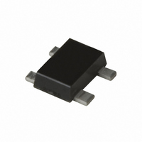
NE664M04-A CEL, NE664M04-A Datasheet - Page 3

NE664M04-A
Manufacturer Part Number
NE664M04-A
Description
TRANSISTOR NPN 1.8GHZ M04
Manufacturer
CEL
Datasheet
1.NE664M04-A.pdf
(10 pages)
Specifications of NE664M04-A
Transistor Type
NPN
Voltage - Collector Emitter Breakdown (max)
5V
Frequency - Transition
20GHz
Gain
12dB
Power - Max
735mW
Dc Current Gain (hfe) (min) @ Ic, Vce
40 @ 100mA, 3V
Current - Collector (ic) (max)
500mA
Mounting Type
Surface Mount
Package / Case
M04
Dc Collector/base Gain Hfe Min
60
Mounting Style
SMD/SMT
Configuration
Single
Transistor Polarity
NPN
Collector- Emitter Voltage Vceo Max
5 V
Emitter- Base Voltage Vebo
1.5 V
Continuous Collector Current
0.5 A
Power Dissipation
0.735 W
Lead Free Status / RoHS Status
Lead free / RoHS Compliant
Noise Figure (db Typ @ F)
-
Lead Free Status / Rohs Status
Lead free / RoHS Compliant
TYPICAL PERFORMANCE CURVES
0.001
1000
1000
1000
0.01
800
600
400
200
100
735
100
205
0.1
10
10
1
0.5
0
1
Mounted on Polyimide PCB
(38 x 38 mm, t = 0.4 mm)
Stand alone device
in free air
V
TOTAL POWER DISSIPATION vs.
CE
Base to Emitter Voltage, V
BASE TO EMITTER VOLTAGE
Ambient Temperature, T
COLLECTOR CURRENT vs.
= 3 V
25
AMBIENT TEMPERATURE
0.6
Collector Current, I
COLLECTOR CURRENT
DC CURRENT GAIN vs.
10
50
0.7
75
0.8
100
100
C
(mA)
A
BE
(ºC)
0.9
V
125
CE
(V)
= 3 V
1000
150
1.0
(T
A
= 25°C)
450
400
350
300
250
200
150
100
2.0
1.5
1.0
0.5
50
REVERSE TRANSFER CAPACITANCE vs.
0
0
COLLECTOR TO EMITTER VOLTAGE
Collector to Emitter Voltage, V
COLLECTOR TO BASE VOLTAGE
Collector to Base Voltage, V
COLLECTOR CURRENT vs.
1
1
2
7 mA
6 mA
2
5 mA
3
4 mA
3
3 mA
4
I
B
: 0.5 mA step
f = 1 MHz
I
B
CB
= 0.5 mA
4
CE
2 mA
5
(V)
1 mA
(V)
5
6


