790163-1 TE Connectivity, 790163-1 Datasheet - Page 4
790163-1
Manufacturer Part Number
790163-1
Description
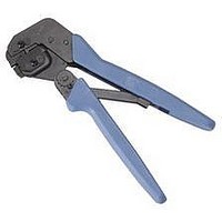
HAND TOOL ASSEMBLY AND DIE ASSEMBLY
Manufacturer
TE Connectivity
Type
Hand Toolr
Specifications of 790163-1
Rohs Compliant
NA
Lead Free Status / RoHS Status
RoHS Not Applicable


6. MAINTENANCE AND INSPECTION
6.1. Daily Maintenance
It is recommended that the tool operator be made
aware of, and are responsible for, the following steps
of daily maintenance.
6.2. Periodic Inspection
Regular inspection of the tool should be performed by
quality control personnel. A record of the scheduled
inspections should remain with the tool or be supplied
to personnel responsible for the tool. Inspection
frequency should be based on amount of use,
working conditions, operator training and skill, and
established company standards.
4 of 4
PRO-CRIMPER III Hand Tool Assembly 1976319-1 with Die Assembly 1976320-1
NOTE
2. Close the tool handles until the ratchet releases,
then allow the handles to open FULLY. Insert a
modular plug (without cable) into the crimping
chamber.
3. Close the tool handles, and hold.
4. Insert a key into the socket head cap screw
(retaining the wire stuffer), and tighten the screw.
5. Allow the handles to open, and remove the
crimped modular plug. The wire stuffer will be held
in its proper position.
1. Remove dust, moisture, and any other
contaminants from the tool with a clean, soft brush,
or a clean, soft, lint–free cloth. DO NOT use hard
or abrasive objects that could damage the tool.
2. Make certain that the retaining pins are in place
and that they are secured with retaining rings.
3. All pins, pivot points, and bearing surfaces
should be protected with a thin coat of any good
grade SAE 20 motor oil. DO NOT oil excessively.
4. When the tool is not in use, keep the handles
closed to prevent objects from becoming lodged in
the jaws.
5. Store the tool in a clean, dry area.
i
DO NOT tighten the screw. If the screw is tight,
loosen it.
Tyco Electronics Corporation
6.3. Visual Inspection
7. REPLACEMENT
Customer–replaceable parts are shown in Figure 1.
Available separately, Repair Kit 679221–1 includes a
replacement nut and a variety of pins, rings, screws,
and springs. If the die assembly is damaged or worn
excessively, it must be replaced. Order the repair kit
and replaceable parts through your representative, or
call 1–800–526–5142, or send a facsimile of your
purchase order to 717–986–7605, or write to:
8. REVISION SUMMARY
Revisions to this instruction sheet include:
1. Remove all lubrication and accumulated film by
immersing the tool (handles partially closed) in a
suitable commercial degreaser that will NOT affect
paint or plastic material.
2. Make certain that the retaining pins are in place
and that they are secured with retaining rings.
3. Close the tool handles until the ratchet releases,
and then allow the handles to open freely. If they
do not open quickly and fully, the spring is
defective and must be replaced.
4. Inspect the tool frame for wear or damage,
paying particular attention to the tool jaws and the
pivot points. If damage is evident, replace it. If
damage is not evident, lubricate the pivot point and
return the tool to service.
5. Check the die assembly on a regular basis to
ensure it has not become worn or damaged.
Inspect the crimping sections for flattened,
chipped, worn, or broken areas. If damage is
evident, replace the die assembly.
CUSTOMER SERVICE (038–035)
TYCO ELECTRONICS CORPORATION
PO BOX 3608
HARRISBURG PA 17105–3608
S Added modular plug part numbers
S Corrected modular plug part number in
S Changed hand tool frame part number
S Added document references to Section 4
S Replaced Section 5 with Step 4 of Section 4
S Removed Section 9
Figure 1
408-8738
Rev D