9-1393792-0 TE Connectivity, 9-1393792-0 Datasheet - Page 464
9-1393792-0
Manufacturer Part Number
9-1393792-0
Description
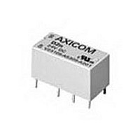
Electromechanical Relay DPDT 3A 24VDC 3.872KOhm Through Hole
Manufacturer
TE Connectivity
Type
Signal Relayr
Specifications of 9-1393792-0
Contact Arrangement
DPDT
Dc Coil Voltage
24 V
Coil Current
6.2 mA
Mounting
Through Hole
Relay Construction
Non-Latching
Coil Voltage Dc
24V
Contact Form
2 Form C
Voltage Rating (vdc)
220V
Voltage Rating (vac)
250V
Dropout Volt (min)
1.2VDCV
Coil Resistance
3.872kohm
Pick-up Voltage (max)
19.2VDC
Maximum Power Rating
60W/125VA
Operate Time
5ms
Contact Current Rating
3A
Contact Material
AgNi/Au
Coil Suppression Diode
No
Push To Test Button
No
Led Indicator
No
Seal
Unsealed
Product Height (mm)
11mm
Product Depth (mm)
10mm
Product Length (mm)
20.2mm
Operating Temp Range
-25C to 85C
Pin Count
8
Mounting Style
Through Hole
Termination Style
PC Pin
Package / Case
DIP
Lead Free Status / Rohs Status
Compliant


1308
Specifications common to all models
Power Consumption: 2.5VA, maximum.
Contact Ratings: 5 amps, resistive, at 120VAC.
Isolation from Control to Sense Inputs: 2,500VAC.
Mechanical Life: 10 million operations.
Shock: 10g.
Vibration: 0.062 (1.57) double amplitude at 10-55 Hz.
Terminals: M3.5 screws.
Maximum Wire Size: 2 x 24 AWG (2.5mm
AWG (1.5mm
Operating Temperature Range: -40 C to +60 C.
Enclosure: Plastic case (not sealed).
Mounting Options: Snap mounts on standard DIN rail (DIN-EN 50022-35)
or panel mounts with M4, M5, #8 or #10 screws.
Weight: 14.4 oz. (400g) approximately.
Overview
The WD series offers several different models of protective relays in a
common package that is suitable for either DIN rail or screw mounting.
These flexible, multifunction devices offer user selectable voltages, sense
currents and frequencies. Adjustable time delays are standard. This allows
a single part number to be suitable for multiple applications, thereby reduc-
ing inventory costs.
Installation and Maintenance Information
Installation: To mount the WD series protective relay on a DIN rail, hook
the top edge of the cutout on the base of the case over one edge of the
DIN rail, then press the opposite side of the cutout containing the release
clip over the opposite side of the DIN rail. To remove or reposition the re-
lay, lever the release clip and move the relay as required. WD series relays
should be installed in a dry location where the ambient temperature will be
within the operating temperature range.
Maintenance: WD series protective relays are solid state devices that re-
quire no maintenance. They are not designed to be serviced by the user.
Consult KILOVAC customer service at 805-220-2023 if repairs should be
necessary.
Dimensions are shown for
reference purposes only.
2
) stranded w/end sleeves.
5 amps, resistive, at 30VDC.
2
Dimensions are in inches over
(millimeters) unless otherwise
specified.
) solid to DIN 46288 or 2 x 16
Catalog 1308242
Issued 3-03
Outline Dimensions
WD
DIN Rail or Screw Mounted
Protective Relays
• WD25 Paralleling (Synch Check) Relays
• WD2759 Over/undervoltage Relays
• WD32 Reverse Power Relays
• WD47 Phase Sequence Relays
• WD5051 Single- or Three-Phase Overcurrent Relays
• WD81OU Over/Underfrequency Relays
Users should thoroughly review the technical data before selecting a product part
number. It is recommended that user also seek out the pertinent approvals files of
the agencies/laboratories and review them to ensure the product meets the
requirements for a given application.
File E58048
(60.0)
Specifications and availability
subject to change.
2.36
(9.0)
0.35
(112.0)
(50.0)
series
1.97
(73.0)
4.41
2.87
M5
M4
DIN EN50022-35
(75.0)
(60.0)
2.95
2.36
16 X M3.5
(35.0)
1.38
www.tycoelectronics.com
Technical support:
Refer to inside back cover.
KILOVAC
Related parts for 9-1393792-0
Image
Part Number
Description
Manufacturer
Datasheet
Request
R

Part Number:
Description:
CRIMP, RECEPTACLE
Manufacturer:
TE Connectivity
Datasheet:

Part Number:
Description:
PIGGYBACK DISCONNECT, 6.35MM, CRIMP BLUE
Manufacturer:
TE Connectivity
Datasheet:

Part Number:
Description:
Manufacturer:
TE Connectivity
Datasheet:

Part Number:
Description:
CRIMP TERMINAL, FEMALE, BLUE
Manufacturer:
TE Connectivity
Datasheet:
Part Number:
Description:
Manufacturer:
TE Connectivity
Datasheet:

Part Number:
Description:
CONN HEADR BRKWAY .100 13POS R/A
Manufacturer:
Tyco Electronics
Datasheet:
Part Number:
Description:
CONN HEADR BRKWAY .100 13POS R/A
Manufacturer:
Tyco Electronics
Datasheet:
Part Number:
Description:
CONN HDR BRKWAY .100 13POS VERT
Manufacturer:
Tyco Electronics
Datasheet:
Part Number:
Description:
CONN HDR BRKWAY .100 13POS VERT
Manufacturer:
Tyco Electronics
Datasheet:
Part Number:
Description:
CONN HDR BRKWAY .100 13POS VERT
Manufacturer:
Tyco Electronics
Datasheet:
Part Number:
Description:
CONN HEADR BRKWAY .100 13POS R/A
Manufacturer:
Tyco Electronics
Datasheet:
Part Number:
Description:
CONN HEADR BRKWAY .100 13POS STR
Manufacturer:
Tyco Electronics
Datasheet:
Part Number:
Description:
CONN HEADR BRKWAY .100 13POS STR
Manufacturer:
Tyco Electronics
Datasheet:
Part Number:
Description:
CONN HEADR BRKWAY .100 13POS STR
Manufacturer:
Tyco Electronics
Datasheet:
Part Number:
Description:
CONN HEADR BRKWAY .100 13POS R/A
Manufacturer:
Tyco Electronics
Datasheet: