9-1393792-0 TE Connectivity, 9-1393792-0 Datasheet - Page 56
9-1393792-0
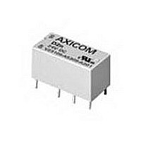
Manufacturer Part Number
9-1393792-0
Description
Electromechanical Relay DPDT 3A 24VDC 3.872KOhm Through Hole
Manufacturer
TE Connectivity
Type
Signal Relayr
Specifications of 9-1393792-0
Contact Arrangement
DPDT
Dc Coil Voltage
24 V
Coil Current
6.2 mA
Mounting
Through Hole
Relay Construction
Non-Latching
Coil Voltage Dc
24V
Contact Form
2 Form C
Voltage Rating (vdc)
220V
Voltage Rating (vac)
250V
Dropout Volt (min)
1.2VDCV
Coil Resistance
3.872kohm
Pick-up Voltage (max)
19.2VDC
Maximum Power Rating
60W/125VA
Operate Time
5ms
Contact Current Rating
3A
Contact Material
AgNi/Au
Coil Suppression Diode
No
Push To Test Button
No
Led Indicator
No
Seal
Unsealed
Product Height (mm)
11mm
Product Depth (mm)
10mm
Product Length (mm)
20.2mm
Operating Temp Range
-25C to 85C
Pin Count
8
Mounting Style
Through Hole
Termination Style
PC Pin
Package / Case
DIP
Lead Free Status / Rohs Status
Compliant


120
Time vs. Current Trip Curves For W6 Series and W9 Series
AC 50/60 Hz.
DC
AC/DC
Note:
Pulse tolerance is defined as a single pulse of a half sine
wave (1/2 cycle or 8 milliseconds) that will not trip the
breaker. An inertia wheel for increased pulse tolerance is
available by specifying “P” after the time delay curve
number in the ordering information. The table at right lists
pulse tolerance values of standard and inertia delay models.
Pulse Tolerance Specifications
Dimensions are shown for
reference purposes only.
10,000
10,000
10,000
10,000
1000
1000
.001
1000
1000
For instantaneous curves for all voltages refer to Curve 0 Non-Time Delay under the AC 50/60 Hz. heading.
100
.001
.001
.001
.01
100
100
100
10
.01
400 Hz.
.01
.01
.1
10
10
10
1
0
.1
.1
.1
1
0
1
0
1
0
125 150
100 200 300 400 500 600 700 800 900 1000 1 100 1200
125 150
100 200 300 400 500 600 700 800 900 1000 1 100 1200
135
125 150
100 200 300 400 500 600 700 800 900 1000 1 100 1200
125 150
100 200 300 400 500 600 700 800 900 1000 1 100 1200
CURVE 34 DC, 50/60 Hz. STANDARD DELAY
CURVE 10 HIGH INRUSH 50/60 Hz. AC
DC & 50/60 Hz.
CURVE 0 NON-TIME DELAY
CURVE 2 DC VOLTAGE
LOAD CURRENT AS A PERCENT
LOAD CURRENT AS A PERCENT
LOAD CURRENT AS A PERCENT
LOAD CURRENT AS A PERCENT
OVERLOAD @ 50/60 Hz. & DC @ 400 Hz.
MOTOR START
OF BREAKER RATING
OF BREAKER RATING
OF BREAKER RATING
OF BREAKER RATING
125%
150%
200%
400%
600%
800%
100 ms max.
55 ms max.
30 ms max.
15 ms max.
12 ms max.
12 ms max.
OVERLOAD TRIP TIMES
OVERLOAD TRIP TIMES
OVERLOAD TRIP TIMES
1000%
125%
1000%
1000%
200%
400%
600%
800%
125%
200%
400%
600%
800%
135%
200%
400%
600%
800%
TRIP TIMES
100 ms max.
.009 - 2
.004 - .025
30 ms max.
15 ms max.
12 ms max.
12 ms max.
.004 - .05
May Trip
.095 - 2
.002 - .45
.002 - .09
40 - 500
.60 - 8
.02 - .5
(SEC.)
.1 - 1.5
.60 - 20
.02 - .95
.8 - 10
.1 - 4.5
(SEC.)
(SEC.)
2 - 55
9 - 100
2 - 20
1 - 90
Dimensions are in inches over
(millimeters) unless otherwise
specified.
10,000
10,000
10,000
10,000
1000
AC 400 Hz.
1000
1000
1000
.001
.001
.001
.001
100
100
100
100
.01
.01
.01
.01
10
10
10
10
.1
.1
1
0
.1
1
0
.1
1
0
1
0
100 200 300 400 500 600 700 800 900 1000 1 100 1200
125 150
100 200 300 400 500 600 700 800 900 1000 1 100 1200
125 150
100 200 300 400 500 600 700 800 900 1000 1 100 1200
125 150
125 150
100 200 300 400 500 600 700 800 900 1000 1 100 1200
CURVE 12 HIGH INRUSH 50/60 Hz.
CURVE 2 AC VOLTAGE 400 Hz.
CURVE 2 AC VOLTAGE 50/60 Hz.
Catalog 1308242
CURVE 3 DC VOLTAGE
LOAD CURRENT AS A PERCENT
LOAD CURRENT AS A PERCENT
LOAD CURRENT AS A PERCENT
LOAD CURRENT AS A PERCENT
Issued 3-03
OF BREAKER RATING
OF BREAKER RATING
OF BREAKER RATING
OF BREAKER RATING
To determine pulse tolerance multiply breaker rating by value in table. For
example, a 2A breaker with time delay curve 3 has a standard pulse tolerance
of 12A (2A x 6). The same breaker with an inertia delay has a pulse tolerance
of 36A (2A x 18).
50/60 Hz.
Specifications and availability
subject to change.
Voltage
400 Hz.
OVERLOAD TRIP TIMES
OVERLOAD TRIP TIMES
OVERLOAD TRIP TIMES
OVERLOAD TRIP TIMES
AC
AC
1000%
1000%
1000%
1000%
125%
200%
400%
600%
800%
150%
200%
400%
600%
800%
125%
200%
400%
600%
800%
125%
200%
400%
600%
800%
.009 - .35
.015 - .7
.005 - .045
.003 - .015
.006 - .06
.004 - .05
.15 - 1
.007 - .15
.005 - .04
10 - 150
2.2 - 20
.01 - .17
.16 - 1.5
.03 - .25
.01 - .13
.5 - 2.5
(SEC.)
(SEC.)
.3 - 3.2
2.2 - 20
.03 - .75
3 - 25
(SEC.)
.6 - 7
(SEC.)
10 - 150
5 - 60
.2 - 2
Curve
Delay
Time
12
13
10
2
3
2
3
10,000
10,000
10,000
10,000
1000
1000
1000
1000
.001
.001
.001
.001
100
100
100
100
.01
.01
.01
.01
10
10
10
10
.1
.1
Standard
1
0
.1
.1
1
0
1
0
1
0
Pulse Tolerance Value
125 150
6.5
5.5
100 200 300 400 500 600 700 800 900 1000 1 100 1200
100 200 300 400 500 600 700 800 900 1000 1 100 1200
125 150
7 .5
125 150
125 150
18
18
18
100 200 300 400 500 600 700 800 900 1000 1 100 1200
100 200 300 400 500 600 700 800 900 1000 1 100 1200
6
CURVE 13 HIGH INRUSH 50/60 Hz.
CURVE 3 AC VOLTAGE 50/60 Hz.
CURVE 3 AC VOLTAGE 400 Hz.
CURVE 53 DC HIGH INRUSH
LOAD CURRENT AS A PERCENT
LOAD CURRENT AS A PERCENT
LOAD CURRENT AS A PERCENT
LOAD CURRENT AS A PERCENT
OF BREAKER RATING
OF BREAKER RATING
OF BREAKER RATING
OF BREAKER RATING
Inertia
Delay
18
18
30
30
30
18
18
www.tycoelectronics.com
Technical support:
Refer to inside back cover.
OVERLOAD TRIP TIMES
OVERLOAD TRIP TIMES
OVERLOAD TRIP TIMES
OVERLOAD TRIP TIMES
1000%
1000%
1000%
150%
200%
400%
600%
800%
1000%
125%
200%
400%
600%
800%
125%
200%
400%
600%
800%
125%
200%
400%
600%
800%
.004 - .035
.006 - .075
.004 - .05
.55 - 5.5
.18 - 2
.02 - .2
.009 - .12
.009 - .09
.70 - 10
.10 - 3
.01 - .1
.007 - .15
.003 - .08
.003 - .04
80 - 700
15 - 150
P&B
(SEC.)
.15 - 2.5
.03 - .3
.02 - .15
(SEC.)
(SEC.)
.15 - 1.5
.03 - .25
(SEC.)
2 - 20
.8 - 30
1 - 15
Related parts for 9-1393792-0
Image
Part Number
Description
Manufacturer
Datasheet
Request
R

Part Number:
Description:
CRIMP, RECEPTACLE
Manufacturer:
TE Connectivity
Datasheet:

Part Number:
Description:
PIGGYBACK DISCONNECT, 6.35MM, CRIMP BLUE
Manufacturer:
TE Connectivity
Datasheet:

Part Number:
Description:
Manufacturer:
TE Connectivity
Datasheet:

Part Number:
Description:
CRIMP TERMINAL, FEMALE, BLUE
Manufacturer:
TE Connectivity
Datasheet:
Part Number:
Description:
Manufacturer:
TE Connectivity
Datasheet:

Part Number:
Description:
CONN HEADR BRKWAY .100 13POS R/A
Manufacturer:
Tyco Electronics
Datasheet:
Part Number:
Description:
CONN HEADR BRKWAY .100 13POS R/A
Manufacturer:
Tyco Electronics
Datasheet:
Part Number:
Description:
CONN HDR BRKWAY .100 13POS VERT
Manufacturer:
Tyco Electronics
Datasheet:
Part Number:
Description:
CONN HDR BRKWAY .100 13POS VERT
Manufacturer:
Tyco Electronics
Datasheet:
Part Number:
Description:
CONN HDR BRKWAY .100 13POS VERT
Manufacturer:
Tyco Electronics
Datasheet:
Part Number:
Description:
CONN HEADR BRKWAY .100 13POS R/A
Manufacturer:
Tyco Electronics
Datasheet:
Part Number:
Description:
CONN HEADR BRKWAY .100 13POS STR
Manufacturer:
Tyco Electronics
Datasheet:
Part Number:
Description:
CONN HEADR BRKWAY .100 13POS STR
Manufacturer:
Tyco Electronics
Datasheet:
Part Number:
Description:
CONN HEADR BRKWAY .100 13POS STR
Manufacturer:
Tyco Electronics
Datasheet:
Part Number:
Description:
CONN HEADR BRKWAY .100 13POS R/A
Manufacturer:
Tyco Electronics
Datasheet: