NUS5531MTR2G ON Semiconductor, NUS5531MTR2G Datasheet - Page 2
NUS5531MTR2G
Manufacturer Part Number
NUS5531MTR2G
Description
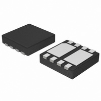
MOSFET/BJT SGL P-CH 12V 8-WDFN
Manufacturer
ON Semiconductor
Datasheet
1.NUS5531MTR2G.pdf
(10 pages)
Specifications of NUS5531MTR2G
Transistor Type
PNP, P-Channel
Applications
General Purpose
Voltage - Rated
20V PNP, 12V P-Channel
Current Rating
2A PNP, 5.47A P-Channel
Mounting Type
Surface Mount
Package / Case
8-WDFN Exposed Pad
Lead Free Status / RoHS Status
Lead free / RoHS Compliant
Available stocks
Company
Part Number
Manufacturer
Quantity
Price

Part Number:
NUS5531MTR2G
Manufacturer:
ON/安森美
Quantity:
20 000


Stresses exceeding Maximum Ratings may damage the device. Maximum Ratings are stress ratings only. Functional operation above the
Recommended Operating Conditions is not implied. Extended exposure to stresses above the Recommended Operating Conditions may affect
device reliability.
1. Surface−mounted on FR4 board using 1 in sq pad size (Cu area = 1.127 sq in [1 oz] including traces).
2. Surface−mounted on FR4 board using 0.5 in sq pad size, 1 oz. Cu.
3. Surface−mounted on FR4 board using 50 sq mm pad size, 1 oz. Cu.
THERMAL RESISTANCE RATINGS
OFF CHARACTERISTICS
ON CHARACTERISTICS (Note 4)
P−Channel Power MOSFET Maximum Ratings
P−Channel MOSFET Electrical Characteristics
4. Pulsed Condition: Pulse Width = 300 msec, Duty Cycle ≤ 2%
Drain−to−Source Voltage
Gate−to−Source Voltage
Continuous Drain Current (Note 1)
Power Dissipation (Note 1)
Continuous Drain Current (Note 2)
Power Dissipation (Note 3)
Pulsed Drain Current
Operating Junction and Storage Temperature
Operating Case Temperature (Note 3)
Source Current (Body Diode)
Lead Temperature for Soldering Purposes (1/8″ from case for 10 s)
Junction−to−Ambient – Steady State (Note 3)
Junction−to−Ambient – t < 10 s (Note 3)
Junction−to−Ambient – Steady State (Note 1)
Junction−to−Ambient – t < 10 s (Note 1)
Junction−to−Case – t < 10 s (Note 3)
Drain−to−Source Breakdown Voltage
Drain−to−Source Breakdown
Voltage Temperature Coefficient
Zero Gate Voltage Drain Current
Gate−to−Source Leakage Current
Gate Threshold Voltage
Negative Threshold Temperature Coefficient
Drain−to−Source On Resistance
Forward Transconductance
Parameter
2
Parameter
Parameter
V
V
V
(BR)DSS
Symbol
V
GS(TH)
R
(BR)DSS
I
I
GS(TH)
DS(on)
DSS
GSS
g
FS
/T
/T
(T
(T
http://onsemi.com
J
J
J
J
= 25°C unless otherwise stated)
= 25°C unless otherwise specified)
Steady State
Steady State
Steady State
V
V
DS
I
V
V
V
GS
V
t ≤ 10 s
D
V
t ≤ 5 s
V
GS
GS
GS
GS
DS
2
= −250 mA, ref to 25°C
= −12 V
DS
= 0 V,
Test Condition
= −4.5 V, I
= −2.5 V, I
= 0 V, I
= V
= −16 V, I
= 0 V, V
T
t
p
DS
A
= 10 ms
= 25°C
, I
D
D
GS
= −250 mA
D
= −250 mA
D
D
T
T
T
T
T
T
T
T
= −3.0 A
J
= −3.0 A
= −3.0 A
= ±8 V
A
A
A
A
A
A
J
= 125°C
= 25°C
= 25°C
= 85°C
= 25°C
= 25°C
= 25°C
= 85°C
−12.0
−0.45
Min
T
Symbol
Symbol
J
V
R
R
R
R
V
, T
y
I
P
P
T
T
DSS
DM
I
I
I
qJA
qJA
qJA
qJA
GS
JC
D
D
S
D
D
C
L
STG
−10.1
−0.67
Typ
2.68
5.9
32
44
−55 to 150
−55 to 125
Value
−5.47
0.418
Max
81.4
85.5
58.7
±8.0
−4.0
−6.2
1.46
−4.4
−3.2
−2.8
299
−12
−25
260
2.1
26
±200
Max
−1.0
−10
−1.1
40
50
mV/°C
mV/°C
Units
Units
°C/W
°C/W
°C/W
°C/W
°C/W
Unit
mA
nA
mW
°C
°C
°C
W
W
V
V
V
A
A
A
A
V
S
Related parts for NUS5531MTR2G
Image
Part Number
Description
Manufacturer
Datasheet
Request
R

Part Number:
Description:
ON Semiconductor [VOLTAGE REGULATOR]
Manufacturer:
ON Semiconductor
Datasheet:
Part Number:
Description:
357-036-542-201 CARDEDGE 36POS DL .156 BLK LOPRO
Manufacturer:
ON Semiconductor
Datasheet:
Part Number:
Description:
357-036-542-201 CARDEDGE 36POS DL .156 BLK LOPRO
Manufacturer:
ON Semiconductor
Datasheet:
Part Number:
Description:
357-036-542-201 CARDEDGE 36POS DL .156 BLK LOPRO
Manufacturer:
ON Semiconductor
Datasheet:
Part Number:
Description:
357-036-542-201 CARDEDGE 36POS DL .156 BLK LOPRO
Manufacturer:
ON Semiconductor
Datasheet:
Part Number:
Description:
357-036-542-201 CARDEDGE 36POS DL .156 BLK LOPRO
Manufacturer:
ON Semiconductor
Datasheet:
Part Number:
Description:
357-036-542-201 CARDEDGE 36POS DL .156 BLK LOPRO
Manufacturer:
ON Semiconductor
Datasheet:
Part Number:
Description:
357-036-542-201 CARDEDGE 36POS DL .156 BLK LOPRO
Manufacturer:
ON Semiconductor
Datasheet:
Part Number:
Description:
357-036-542-201 CARDEDGE 36POS DL .156 BLK LOPRO
Manufacturer:
ON Semiconductor
Datasheet:
Part Number:
Description:
357-036-542-201 CARDEDGE 36POS DL .156 BLK LOPRO
Manufacturer:
ON Semiconductor
Datasheet:
Part Number:
Description:
357-036-542-201 CARDEDGE 36POS DL .156 BLK LOPRO
Manufacturer:
ON Semiconductor
Datasheet:
Part Number:
Description:
Manufacturer:
ON Semiconductor
Datasheet:
Part Number:
Description:
Manufacturer:
ON Semiconductor
Datasheet:
Part Number:
Description:
Manufacturer:
ON Semiconductor
Datasheet: