1469025-2 TE Connectivity, 1469025-2 Datasheet - Page 2
1469025-2
Manufacturer Part Number
1469025-2
Description
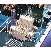
Conn Backplane HDR 40 POS 2.5mm Press Fit ST Thru-Hole
Manufacturer
TE Connectivity
Type
Backplaner
Series
Z-PACKr
Specifications of 1469025-2
Pitch
2.5 mm
Number Of Rows
4
Number Of Contacts
40
Termination Method
Press Fit
Mounting
Through Hole
Contact Plating
Gold Over Nickel
Connector Type
Hard Metric (HM)
Row Pitch
2mm
Pitch Spacing
2mm
No. Of Contacts
40
Gender
Header
Contact Termination
Press Fit
No. Of Rows
4
Rohs Compliant
Yes
Product Type
Male
Number Of Positions / Contacts
40
Termination Style
Press Fit
Housing Material
Polyester, Glass Filled
Contact Material
Copper Nickel Silicon
Mounting Style
Through Hole
Pcb Mounting Orientation
Vertical
Shield Material
Phosphor bronze
Module Length (mm [in])
24.90 [0.980]
Interface Type
HM-Zd
Termination End Plating
Tin-Lead over Nickel
Card Slot Pitch (mm [in])
20.3 [0.8]
Columns Per Connector
10
Centerline (mm [in])
2.50 [0.098]
Selectively Loaded
No
Number Of Positions
40
Contact Type
Pin
Contact Termination Type
Through Hole
Contact Configuration
ACTION PIN Post
Feedthrough Post Length (mm [in])
2.50 [0.098]
Contact Mating Area Length (mm [in])
3.80 [0.150]
Contact Base Material
Phosphor Bronze
Number Of Pairs Per Column
2
Number Of Pairs Per Connector
20
Sequenced Pins
No
Advancedtca Specified Product
No
Rohs/elv Compliance
RoHS compliant, ELV compliant
Lead Free Solder Processes
Not relevant for lead free process
Rohs/elv Compliance History
Always was RoHS compliant
Lead Free Status / Rohs Status
Details


3.2.
3.3.
3.4.
3.5.
Rev C
Initial exam ination of product.
Final exam ination of product.
Low level contact resistance.
Low level com pliant pin resistance.
Insulation resistance.
Materials
Materials used in the construction of this product shall be as specified on the applicable product
drawing.
Ratings
!
!
!
Perform ance and Test Description
Product is designed to m eet the electrical, m echanical and environm ental perform ance requirem ents
specified in Figure 1. Unless otherwise specified, all tests shall be perform ed at am bient environm ental
conditions per EIA-364.
Test Requirem ents and Procedures Sum m ary
Test Description
Operating Voltage: 250 volts AC m axim um peak (a of m inim um breakdown voltage)
Current: .7 am pere per contact (fully loaded)
Tem perature: -65 to 105°C
Meets requirem ents of product
drawing.
Meets visual requirem ents.
20 m illiohm s m axim um initial for
right angle receptacle and vertical
header.
50 m illiohm s m axim um initial for
right angle receptacle and right
angle header.
ÄR < 5 m illiohm s average final.
ÄR < 10 m illiohm s individual
reading final (applies to both signal
and ground contacts).
1 m illiohm m axim um initial.
ÄR = 1 m illiohm m axim um change
from initial.
10000 m egohm s m inim um .
Figure 1 (continued)
ELECTRICAL
Requirem ent
EIA-364-18.
EIA-364-21.
EIA-364-18.
Visual and dim ensional © of C)
inspection per product drawing.
Visual inspection.
EIA-364-23.
Subject specim ens to 100
m illiam peres m axim um and 20
m illivolts m axim um open circuit
voltage.
See Figure 3.
EIA-364-23.
Subject specim ens to 100
m illiam peres m axim um and 20
m illivolts m axim um open circuit
voltage. Measurem ents shall be
taken between PCB hole and pin
tip.
Test between any adjacent signal
contacts, and between any signal
contact and adjacent ground
contacts at 100 volts DC.
Specim ens shall be fully m ated.
Procedure
108-2055
2 of 8
Related parts for 1469025-2
Image
Part Number
Description
Manufacturer
Datasheet
Request
R

Part Number:
Description:
Printers THERMAL PRINTER HS-SLEEVE MARKER
Manufacturer:
TE Connectivity


Part Number:
Description:
High Speed / Modular Connectors 30P HEADER ASSY
Manufacturer:
TE Connectivity
Datasheet:

Part Number:
Description:
High Speed / Modular Connectors REC 6X005P R/A LT B-PLANE HS3
Manufacturer:
TE Connectivity
Datasheet:

Part Number:
Description:
High Speed / Modular Connectors 2MM HM RCPT 50P R/A AU
Manufacturer:
TE Connectivity
Datasheet:

Part Number:
Description:
High Speed / Modular Connectors 2MM HM RCPT 50P R/A AU
Manufacturer:
TE Connectivity
Datasheet:


Part Number:
Description:
Manufacturer:
TE Connectivity
Datasheet:


Part Number:
Description:
Manufacturer:
TE Connectivity
Datasheet:

Part Number:
Description:
Manufacturer:
TE Connectivity
Datasheet:

Part Number:
Description:
Manufacturer:
TE Connectivity
Datasheet: