W2S130-AA25-01 EBM-Papst Industries Inc, W2S130-AA25-01 Datasheet - Page 6
W2S130-AA25-01
Manufacturer Part Number
W2S130-AA25-01
Description
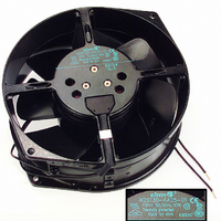
FAN EXHAUST 150 X 55MM 115VAC
Manufacturer
EBM-Papst Industries Inc
Series
W2S130r
Type
Roundr
Datasheets
1.W2S130-AA25-01.pdf
(5 pages)
2.W2S130-AA25-01.pdf
(9 pages)
3.W2S130-AA25-44.pdf
(1 pages)
4.W2S130-AA03-01.pdf
(1 pages)
Specifications of W2S130-AA25-01
Current Type
AC
Supply Voltage
115 V
Bearing Type
Ball
Termination Style
53 dB(A)
Fan Type
Tubeaxial
Size / Dimension
Round - 150mm Dia x 55mm W
Voltage Rating
115VAC
Power (watts)
38W
Rpm
3250 RPM
Noise
53 dB(A)
Air Flow
223.6 CFM (6.33m³/min)
Termination
2 Wire Leads
Weight
2.5 lbs (1.1kg)
Speed
3250 RPM
Frame Dimensions (mm)
150 mm x 55 mm
Housing Material
Aluminum Die-Cast
Power Rating
38 W
External Depth
55mm
External Diameter
150mm
Flow Rate
225CFM
Noise Rating
52dBA
Power Connection Type
Lead Wires
Diameter
150mm
Brand/series
W2S130
Dimensions
5.91 x 2.17 "
Direction
Exhaust over Struts
Noise Level
53 dBA
Power, Rating
38 W
Size
5.91 x 2.17 (150 x 55) In. (mm)
Temperature, Operating, Maximum
+80 °C
Voltage, Rating
115 VAC
Flow Rate - Imperial
225CFM
Rohs Compliant
Yes
Lead Free Status / RoHS Status
Lead free / RoHS Compliant
Static Pressure
-
Lead Free Status / Rohs Status
Lead free / RoHS Compliant
Other names
381-1121
W2S130AA2501
W2S130AA2501
Available stocks
Company
Part Number
Manufacturer
Quantity
Price
Company:

Part Number:
W2S130-AA25-01
Manufacturer:
OMRON
Quantity:
50


4. CONNECTION AND START-UP
4.1 Connecting the mechanical system
4.2 Connecting the electrical system
4.2.1 Prerequisites
4.2.2 Voltage control
Item no.: 10953-5-9970 · Revision status: KM70969 · Print-out on 29/10/2010 · Created by A. Kehm (VM---) · Page 6 of 9
ebm-papst Mulfingen GmbH & Co. KG · Bachmühle 2 · D-74673 Mulfingen · Phone: +49(0)7938/81-0 · Fax: +49(0)7938/81-110 · info1@de.ebmpapst.com · www.ebmpapst.com
W2S130-AA25-01
Install the device according to your application.
Check whether the data on the type plate agree with the connection
data.
Before connecting the device, ensure that the supply voltage matches
the operating voltage of the device.
Only use cables designed for current according to the type plate.
CAUTION
Cutting and crushing hazard when removing the fan
from the packaging
DANGER
Electric voltage on the device
Electric shock
CAUTION
Electrical voltage
The fan is a built-in component and features no electrically
isolating switch.
NOTE
Water penetration into leads or wires
Water enters at the cable end on the customers side and can
damage the device.
Connect the device only to circuits that can be switched off
using an all-pole disconnecting switch.
With open loop speed control using transformers or electronic
voltage regulators (e.g. phase angle control), excessive current
may occur.
In addition, noises can occur with phase angle control
depending on the mounting situation.
Carefully lift the fan out of its packaging, only touching the
housing. Make sure to avoid any shock.
Wear safety shoes and cut-resistant safety gloves.
Always install a protective earth.
Check the protective earth.
Only connect the fan to circuits that can be switched off with
an all-pole separating switch.
When working on the fan, you must switch off the
installation/machine in which the fan is installed and secure it
from being switched on again.
Make sure that the cable end is connected in a dry
environment.
Operating instructions
4.2.3 Frequency inverter
4.3 Connection of the cables
External leads are brought out of device.
Connect the lines according to your application. When doing so,
observe chapter 4.4 Connection diagram.
Fit sinusoidal filters that work on all poles (live-live and live-
earth) between the frequency inverter and the motor for
operation with frequency inverters.
Depending on how the device is installed, noises may occur.
Related parts for W2S130-AA25-01
Image
Part Number
Description
Manufacturer
Datasheet
Request
R

Part Number:
Description:
FAN INTAKE 150 X 55MM 115VAC
Manufacturer:
EBM-Papst Industries Inc
Datasheet:

Part Number:
Description:
FAN EXHAUST 150 X 55MM 115VAC
Manufacturer:
EBM-Papst Industries Inc
Datasheet:

Part Number:
Description:
FAN TUBEAXIAL 150X55MM 230VAC
Manufacturer:
EBM-Papst Industries Inc
Datasheet:

Part Number:
Description:
FAN TUBEAXIAL 150X55MM 230VAC
Manufacturer:
EBM-Papst Industries Inc
Datasheet:
Part Number:
Description:
FAN TUBEAXIL 150X55MM 115/230VAC
Manufacturer:
EBM-Papst Industries Inc
Datasheet:

Part Number:
Description:
FAN INTAKE 150 X 55MM 230VAC
Manufacturer:
EBM-Papst Industries Inc
Datasheet:

Part Number:
Description:
Fans
Manufacturer:
EBM-Papst Industries Inc
Datasheet:
Part Number:
Description:
FAN TUBEAXIAL 150X55MM 115VAC
Manufacturer:
EBM-Papst Industries Inc
Datasheet:

Part Number:
Description:
AXIAL FAN, 150MM, 115VAC
Manufacturer:
EBM-Papst Industries Inc
Part Number:
Description:
AXIAL FAN, 150MM, 230VAC
Manufacturer:
EBM-Papst Industries Inc
Datasheet:

Part Number:
Description:
FAN EXHAUST 119 X 25MM 230VAC
Manufacturer:
EBM-Papst Industries Inc
Datasheet:

Part Number:
Description:
FAN TUBEAXIAL 92X38MM 230VAC
Manufacturer:
EBM-Papst Industries Inc
Datasheet:

Part Number:
Description:
FAN 92 X 32MM 12VDC
Manufacturer:
EBM-Papst Industries Inc
Datasheet:

Part Number:
Description:
FAN TUBEAXIAL 40X20MM 5VDC
Manufacturer:
EBM-Papst Industries Inc
Datasheet:

Part Number:
Description:
AC Tubeaxial Fan
Manufacturer:
EBM-Papst Industries Inc
Datasheet: