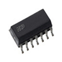
AU5790D14 NXP Semiconductors, AU5790D14 Datasheet - Page 4

AU5790D14
Manufacturer Part Number
AU5790D14
Description
Network Controller & Processor ICs SINGLE WIRE CAN TRANSCEIVER
Manufacturer
NXP Semiconductors
Datasheet
1.AU5790D14518.pdf
(20 pages)
Specifications of AU5790D14
Number Of Transceivers
1
Power Down Mode
Sleep/Standby
Operating Supply Voltage (max)
27V
Operating Supply Voltage (typ)
13V
Operating Supply Voltage (min)
5.3V
Package Type
SO
Supply Current
90mA
Operating Temperature (max)
125C
Operating Temperature (min)
-40C
Operating Temperature Classification
Automotive
Mounting
Surface Mount
Pin Count
14
Product
Controller Area Network (CAN)
Data Rate
83.3 Kbps
Supply Voltage (max)
27 V
Supply Voltage (min)
5.3 V
Supply Current (max)
90 mA
Maximum Operating Temperature
+ 125 C
Minimum Operating Temperature
- 40 C
Mounting Style
SMD/SMT
Package / Case
SO
Lead Free Status / RoHS Status
Compliant
Other names
AU5790D14,512
Available stocks
Company
Part Number
Manufacturer
Quantity
Price
Company:
Part Number:
AU5790D14
Manufacturer:
PHILIPS
Quantity:
844
Part Number:
AU5790D14
Manufacturer:
NXP/恩智浦
Quantity:
20 000
Part Number:
AU5790D14/N
Manufacturer:
NXP/恩智浦
Quantity:
20 000
Philips Semiconductors
SO8 PIN CONFIGURATION
SO8 PIN DESCRIPTION
2001 May 18
TxD
NSTB
(Mode 0)
EN
(Mode 1)
RxD
BAT
RTH
(LOAD)
CANH
(BUS)
GND
SYM-
NSTB (Mode 0)
BOL
Single wire CAN transceiver
EN (Mode 1)
RxD
TxD
PIN
1
2
3
4
5
6
7
8
Transmit data input: high = transmitter passive;
low = transmitter active
Stand-by control: high = normal and
high-speed mode; low = sleep and wake-up
mode
Enable control: high = normal and wake-up
mode; low = sleep and high-speed mode
Receive data output: low = active bus condition
detected; float/high = passive bus condition
detected
Battery supply input (12 V nom.)
Switched ground pin: pulls the load to ground,
except in case the module ground is
disconnected
Bus line transmit input/output
Ground
1
2
3
4
AU5790
DESCRIPTION
SO8
8
7
6
5
GND
CANH (BUS)
RTH (Load)
BAT
SL01198
4
SO14 PIN CONFIGURATION
SO14 PIN DESCRIPTION
GND
TxD
NSTB
(Mode 0)
EN
(Mode 1)
RxD
N.C.
GND
GND
N.C.
BAT
RTH
(LOAD)
CANH
(BUS)
N.C.
GND
SYM-
NSTB (Mode 0)
BOL
EN (Mode 1)
GND
GND
RxD
N.C.
TxD
PIN
10
11
12
13
14
1
2
3
4
5
6
7
8
9
Ground
Transmit data input: high = transmitter passive;
low = transmitter active
Stand-by control: high = normal and
high-speed mode; low = sleep and wake-up
mode
Enable control: high = normal and wake-up
mode; low = sleep and high-speed mode
Receive data output: low = active bus condition
detected; float/high = passive bus condition
detected
No connection
Ground
Ground
No connection
1
2
3
4
5
6
7
Battery supply input (12 V nom.)
Switched ground pin: pulls the load to ground,
except in case the module ground is
disconnected
Bus line transmit input/output
No connection
Ground
AU5790
DESCRIPTION
SO14
AU5790
14
13
12
10
9
11
8
SL01251
Product data
GND
N.C.
CANH (BUS)
RTH (Load)
BAT
N.C.
GND


