MCP635T-E/MF Microchip Technology, MCP635T-E/MF Datasheet - Page 23
MCP635T-E/MF
Manufacturer Part Number
MCP635T-E/MF
Description
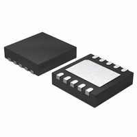
Dual, 24MHz OP W /CS, E Temp 10 DFN 3x3mm T/R
Manufacturer
Microchip Technology
Datasheet
1.MCP631-ESN.pdf
(42 pages)
Specifications of MCP635T-E/MF
Amplifier Type
General Purpose
Number Of Circuits
2
Output Type
Rail-to-Rail
Slew Rate
10 V/µs
Gain Bandwidth Product
24MHz
Current - Input Bias
4pA
Voltage - Input Offset
1800µV
Current - Supply
2.5mA
Current - Output / Channel
70mA
Voltage - Supply, Single/dual (±)
2.5 V ~ 5.5 V
Operating Temperature
-40°C ~ 125°C
Mounting Type
Surface Mount
Package / Case
10-DFN
Number Of Channels
2
Voltage Gain Db
124 dB
Common Mode Rejection Ratio (min)
63 dB
Input Offset Voltage
8 mV
Operating Supply Voltage
3 V, 5 V
Maximum Operating Temperature
+ 125 C
Mounting Style
SMD/SMT
Minimum Operating Temperature
- 40 C
Lead Free Status / RoHS Status
Lead free / RoHS Compliant
-3db Bandwidth
-
Lead Free Status / Rohs Status
Details
Available stocks
Company
Part Number
Manufacturer
Quantity
Price
Company:

Part Number:
MCP635T-E/MF
Manufacturer:
MICROCHIP
Quantity:
12 000


The power de-rating across temperature for an op amp
in a particular package can be easily calculated
(assuming equal power dissipations):
EQUATION 4-5:
Several techniques are available to reduce ΔT
given P
• Lower θ
• Reduce P
4.3
4.3.1
Driving large capacitive loads can cause stability
problems for voltage feedback op amps. As the load
capacitance increases, the feedback loop’s phase
margin decreases and the closed-loop bandwidth is
reduced. This produces gain peaking in the frequency
response, with overshoot and ringing in the step
response. A unity gain buffer (G = +1) is the most
sensitive to capacitive loads, though all gains show the
same general behavior.
When driving large capacitive loads with these op
amps (e.g., > 20 pF when G = +1), a small series
resistor at the output (R
feedback loop’s phase margin (stability) by making the
output load resistive at higher frequencies. The
bandwidth will be generally lower than the bandwidth
with no capacitive load.
FIGURE 4-6:
stabilizes large capacitive loads.
© 2009 Microchip Technology Inc.
Where:
- Use another package
- PCB layout (ground plane, etc.)
- Heat sinks and air flow
- Increase R
- Limit I
- Decrease V
T
Jmax
OAmax
Improving Stability
JA
OUT
R
R
=
CAPACITIVE LOADS
OAmax
G
N
:
(using R
absolute maximum junction temperature
L
DD
P
OAmax
R
MCP63X
F
Output Resistor, R
SER
ISO
≤
T
)
in
Jmax
Figure
R
n
ISO
θ
C
JA
– T
L
A
4-6) improves the
V
OUT
ISO
JA
for a
Figure 4-7
different capacitive loads and gains. The x-axis is the
normalized load capacitance (C
circuit’s noise gain. For non-inverting gains, G
Signal Gain are equal. For inverting gains, G
1+|Signal Gain| (e.g., -1 V/V gives G
FIGURE 4-7:
for Capacitive Loads.
After selecting R
resulting frequency response peaking and step
response overshoot. Modify R
response is reasonable. Bench evaluation and
simulations with the MCP631/2/3/5 SPICE macro
model are helpful.
4.3.2
Figure 4-8
non-inverting amplifiers (V
the input) or inverting amplifiers (V
and V
represent the total capacitance at the input pins; they
include the op amp’s common mode input capacitance
(C
placed in parallel.
FIGURE 4-8:
Capacitance.
C
which causes an increase in gain at high frequencies.
C
loop, which becomes less stable. This effect can be
reduced by either reducing C
G
G
CM
acts in parallel with R
also reduces the phase margin of the feedback
1,000
), board parasitic capacitance and any capacitor
100
M
10
1.E-12
10p
is the input). The capacitances C
V
V
M
P
shows an op amp circuit that represents
GAIN PEAKING
gives recommended R
Normalized Capacitance; C
R
R
ISO
1.E-11
N
G
MCP631/2/3/5
for your circuit, double check the
100p
Recommended R
Amplifier with Parasitic
C
C
G
N
G
(except for a gain of +1 V/V),
M
1.E-10
R
MCP63X
is a DC voltage and V
G
F
G
G
or R
L
N
N
ISO
/G
= +1
≥ +2
N
F
’s value until the
1n
P
.
), where G
N
DS22197A-page 23
1.E-09
ISO
is a DC voltage
= +2 V/V).
L
/G
V
OUT
N
ISO
(F)
values for
N
N
Values
and C
and the
N
1.E-08
10n
is the
N
P
is
is
G
Related parts for MCP635T-E/MF
Image
Part Number
Description
Manufacturer
Datasheet
Request
R

Part Number:
Description:
Dual, 24MHz OP W /CS, E Temp 10 MSOP 3x3mm T/R
Manufacturer:
Microchip Technology
Datasheet:

Part Number:
Description:
Manufacturer:
Microchip Technology Inc.
Datasheet:
Part Number:
Description:
Manufacturer:
Microchip Technology Inc.
Datasheet:
Part Number:
Description:
Manufacturer:
Microchip Technology Inc.
Datasheet:
Part Number:
Description:
Manufacturer:
Microchip Technology Inc.
Datasheet:
Part Number:
Description:
Manufacturer:
Microchip Technology Inc.
Datasheet:
Part Number:
Description:
Manufacturer:
Microchip Technology Inc.
Datasheet:
Part Number:
Description:
Manufacturer:
Microchip Technology Inc.
Datasheet:
Part Number:
Description:
Manufacturer:
Microchip Technology Inc.
Datasheet: