STK11C68-SF25 Cypress Semiconductor Corp, STK11C68-SF25 Datasheet - Page 4
STK11C68-SF25
Manufacturer Part Number
STK11C68-SF25
Description
STK11C68-SF25
Manufacturer
Cypress Semiconductor Corp
Type
NVSRAMr
Datasheet
1.STK11C68-SF45.pdf
(17 pages)
Specifications of STK11C68-SF25
Format - Memory
RAM
Memory Type
NVSRAM (Non-Volatile SRAM)
Memory Size
64K (8K x 8)
Speed
25ns
Interface
Parallel
Voltage - Supply
4.5 V ~ 5.5 V
Operating Temperature
0°C ~ 70°C
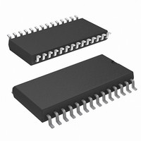
Package / Case
28-SOIC (8.69mm width)
Word Size
8b
Organization
8Kx8
Density
64Kb
Interface Type
Parallel
Access Time (max)
25ns
Operating Supply Voltage (typ)
5V
Package Type
SOIC
Operating Temperature Classification
Commercial
Operating Supply Voltage (max)
5.5V
Operating Supply Voltage (min)
4.5V
Operating Temp Range
0C to 70C
Pin Count
28
Mounting
Surface Mount
Supply Current
90mA
Lead Free Status / RoHS Status
Lead free / RoHS Compliant
Lead Free Status / RoHS Status
Lead free / RoHS Compliant


Device Operation
The STK11C68 is a versatile memory chip that provides several
modes of operation. The STK16C88 can operate as a standard
8K x 8 SRAM. A 8K x 8 array of nonvolatile storage elements
shadow the SRAM. SRAM data can be copied nonvolatile
memory or nonvolatile data can be recalled to the SRAM.
SRAM Read
The STK11C68 performs a Read cycle whenever CE and OE are
LOW while WE is HIGH. The address specified on pins A
determines the 8,192 data bytes accessed. When the Read is
initiated by an address transition, the outputs are valid after a
delay of t
the outputs are valid at t
cycle 2). The data outputs repeatedly respond to address
changes within the t
tions on any control input pins, and remains valid until another
address change or until CE or OE is brought HIGH, or WE
brought LOW.
SRAM Write
A Write cycle is performed whenever CE and WE are LOW. The
address inputs must be stable prior to entering the Write cycle
and must remain stable until either CE or WE goes HIGH at the
end of the cycle. The data on the common I/O pins DQ
written into the memory if it has valid t
controlled Write or before the end of an CE controlled Write.
Keep OE HIGH during the entire Write cycle to avoid data bus
contention on common I/O lines. If OE is left LOW, internal
circuitry turns off the output buffers t
Software STORE
Data is transferred from the SRAM to the nonvolatile memory by
a software address sequence. The STK11C68 software STORE
cycle is initiated by executing sequential CE controlled Read
cycles from six specific address locations in exact order. During
the STORE cycle, an erase of the previous nonvolatile data is
first performed followed by a program of the nonvolatile
elements. When a STORE cycle is initiated, input and output are
disabled until the cycle is completed.
Because a sequence of Reads from specific addresses is used
for STORE initiation, it is important that no other Read or Write
accesses intervene in the sequence. If they intervene, the
sequence is aborted and no STORE or RECALL takes place.
To initiate the software STORE cycle, the following Read
sequence is performed:
The software sequence is clocked with CE controlled Reads.
When the sixth address in the sequence is entered, the STORE
cycle commences and the chip is disabled. It is important that
Read cycles and not Write cycles are used in the sequence. It is
not necessary that OE is LOW for a valid sequence. After the
Document Number: 001-50638 Rev. *A
1. Read address 0x0000, Valid READ
2. Read address 0x1555, Valid READ
3. Read address 0x0AAA, Valid READ
4. Read address 0x1FFF, Valid READ
5. Read address 0x10F0, Valid READ
6. Read address 0x0F0F, Initiate STORE cycle
AA
(Read cycle 1). If the Read is initiated by CE or OE,
AA
access time without the need for transi-
ACE
or at t
DOE
HZWE
SD
, whichever is later (Read
, before the end of a WE
after WE goes LOW.
0–7
0–12
are
t
Read and Write operation.
Software RECALL
Data is transferred from the nonvolatile memory to the SRAM by
a software address sequence. A software RECALL cycle is
initiated with a sequence of Read operations in a manner similar
to the software STORE initiation. To initiate the RECALL cycle,
the following sequence of CE controlled Read operations is
performed:
Internally, RECALL is a two step procedure. First, the SRAM data
is cleared; then, the nonvolatile information is transferred into the
SRAM cells. After the t
ready for Read and Write operations. The RECALL operation
does not alter the data in the nonvolatile elements. The nonvol-
atile data can be recalled an unlimited number of times.
Hardware RECALL (Power Up)
During power up or after any low power condition (V
V
once again exceeds the sense voltage of V
cycle is automatically initiated and takes t
If the STK11C68 is in a Write state at the end of power up
RECALL, the SRAM data is corrupted. To help avoid this
situation, a 10 Kohm resistor is connected either between WE
and system V
Hardware Protect
The STK11C68 offers hardware protection against inadvertent
STORE operation and SRAM Writes during low voltage condi-
tions. When V
operations and SRAM Writes are inhibited.
Noise Considerations
The STK11C68 is a high speed memory. It must have a high
frequency bypass capacitor of approximately 0.1 µF connected
between V
as possible. As with all high speed CMOS ICs, careful routing of
power, ground, and signals reduce circuit noise.
Low Average Active Power
CMOS technology provides the STK11C68 the benefit of
drawing significantly less current when it is cycled at times longer
than 50 ns.
Read or Write cycle time. Worst case current consumption is
shown for both CMOS and TTL input levels (commercial temper-
ature range, VCC = 5.5V, 100% duty cycle on chip enable). Only
standby current is drawn when the chip is disabled.
1. Read address 0x0000, Valid READ
2. Read address 0x1555, Valid READ
3. Read address 0x0AAA, Valid READ
4. Read address 0x1FFF, Valid READ
5. Read address 0x10F0, Valid READ
6. Read address 0x0F0E, Initiate RECALL cycle
STORE
RESET
), an internal RECALL request is latched. When V
cycle time is fulfilled, the SRAM is again activated for
CC
Figure 2
CC
and V
CAP
or between CE and system V
<V
SS,
shows the relationship between I
SWITCH
using leads and traces that are as short
RECALL
, all externally initiated STORE
cycle time, the SRAM is again
HRECALL
SWITCH
STK11C68
CC
.
to complete.
Page 4 of 17
, a RECALL
CC
CC
and
CC
<
[+] Feedback
Related parts for STK11C68-SF25
Image
Part Number
Description
Manufacturer
Datasheet
Request
R

Part Number:
Description:
Manufacturer:
Cypress Semiconductor Corp
Datasheet:

Part Number:
Description:
STK11C68-5K45M
Manufacturer:
Cypress Semiconductor Corp
Datasheet:

Part Number:
Description:
STK11C68-C35I
Manufacturer:
Cypress Semiconductor Corp
Datasheet:

Part Number:
Description:
STK11C68-SF25I
Manufacturer:
Cypress Semiconductor Corp
Datasheet:
Part Number:
Description:
STK11C68-SF25ITR
Manufacturer:
Cypress Semiconductor Corp
Datasheet:
Part Number:
Description:
STK11C68-SF45
Manufacturer:
Cypress Semiconductor Corp
Datasheet: