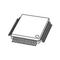
SC16C654DBIB64 NXP Semiconductors, SC16C654DBIB64 Datasheet - Page 21

SC16C654DBIB64
Manufacturer Part Number
SC16C654DBIB64
Description
IC, UART, QUAD, 64BYTE FIFO, 16C654
Manufacturer
NXP Semiconductors
Datasheet
1.SC16C654BIA68.pdf
(58 pages)
Specifications of SC16C654DBIB64
Data Rate
5Mbps
Transmit Fifo
64Byte
Receive Fifo
64Byte
Transmitter And Receiver Fifo Counter
Yes
Package Type
LQFP
Operating Supply Voltage (max)
5.5V
Mounting
Surface Mount
Operating Temperature (min)
-40C
Operating Temperature (max)
85C
Operating Temperature Classification
Industrial
No. Of Channels
4
Supply Voltage Range
2.25V To 5.5V
Operating Temperature Range
-40°C To +85°C
Digital Ic Case Style
LQFP
No. Of Pins
64
Svhc
No SVHC (18-Jun-2010)
Uart Features
Programmable Xon/Xoff Characters, Software Selectable Baud Rate Generator
Rohs Compliant
Yes
Lead Free Status / RoHS Status
Compliant
Available stocks
Company
Part Number
Manufacturer
Quantity
Price
Company:
Part Number:
SC16C654DBIB64,128
Manufacturer:
NXP Semiconductors
Quantity:
10 000
Company:
Part Number:
SC16C654DBIB64,151
Manufacturer:
NXP
Quantity:
144
Company:
Part Number:
SC16C654DBIB64,151
Manufacturer:
NXP Semiconductors
Quantity:
10 000
Company:
Part Number:
SC16C654DBIB64,157
Manufacturer:
NXP Semiconductors
Quantity:
10 000
Company:
Part Number:
SC16C654DBIB64151
Manufacturer:
NXP Semiconductors
Quantity:
135
Philips Semiconductors
9397 750 14965
Product data sheet
SC16C654B/654DB sets the default baud rate table according to the state of the CLKSEL
pin. A logic 1 on CLKSEL will set the 1 clock default, whereas logic 0 will set the 4 clock
default table. Following the default clock rate selection during initialization, the rate tables
can be changed by the internal register MCR[7]. Setting MCR[7] to a logic 1 when
CLKSEL is a logic 1 provides an additional divide-by-4, whereas setting MCR[7] to a
logic 0 only divides by 1; see
achieved by selecting the proper divisor values for the MSB and LSB sections of baud rate
generator.
Programming the Baud Rate Generator Registers DLM (MSB) and DLL (LSB) provides a
user capability for selecting the desired final baud rate. The example in
two selectable baud rate tables available when using a 7.3728 MHz crystal.
Table 7:
Output baud rate
MCR[7] = 1
50
300
600
1200
2400
4800
9600
19.2 k
38.4 k
57.6 k
115.2 k
Fig 11. Baud rate generator circuitry
XTAL1
XTAL2
Baud rate generator programming table using a 7.3728 MHz clock
MCR[7] = 0
200
1200
2400
4800
9600
19.2 k
38.4 k
76.8 k
153.6 k
230.4 k
460.8 k
OSCILLATOR
CLOCK
LOGIC
5 V, 3.3 V and 2.5 V quad UART, 5 Mbit/s (max.) with 64-byte FIFOs
Rev. 02 — 20 June 2005
User
16 clock divisor
Decimal
2304
384
192
96
48
24
12
6
3
2
1
Table 7
DIVIDE-BY-1
DIVIDE-BY-4
and
LOGIC
LOGIC
Figure
HEX
900
180
C0
60
30
18
0C
06
03
02
01
SC16C654B/654DB
11. Customized baud rates can be
MCR[7] = 0
MCR[7] = 1
DLM
program value
(HEX)
09
01
00
00
00
00
00
00
00
00
00
© Koninklijke Philips Electronics N.V. 2005. All rights reserved.
GENERATOR
BAUD RATE
LOGIC
Table 7
DLL
program value
(HEX)
00
80
C0
60
30
18
0C
06
03
02
01
002aaa208
BAUDOUT
shows the
21 of 58


