ATA6823-PHQY Atmel, ATA6823-PHQY Datasheet - Page 6
ATA6823-PHQY
Manufacturer Part Number
ATA6823-PHQY
Description
Motor / Motion / Ignition Controllers & Drivers Gate Driver IC
Manufacturer
Atmel
Type
H-Bridge Motor Driverr
Specifications of ATA6823-PHQY
Operating Current
7mA
Operating Temperature Classification
Automotive
Operating Supply Voltage (min)
7V
Operating Supply Voltage (max)
18V
Supply Current
7 mA
Mounting Style
SMD/SMT
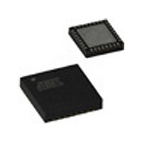
Package / Case
QFN-32
Lead Free Status / RoHS Status
Compliant


3.2
3.3
6
Sleep Mode
Wake-up and Sleep Mode Strategy
Atmel ATA6823
To be able to guarantee the low quiescent current of the inactive IC, a Sleep mode is estab-
lished. In Sleep mode it is possible to wake-up the IC by using the pins EN2 or LIN. In Sleep
mode, the following blocks are active:
The IC has two modes: Sleep and Active. The change between the modes is described below.
The default state after power-on is Active mode.
The wake-up procedure brings the IC from a standby mode (Sleep) to an active mode (Active).
The internal 5V supply VINT, the EN2 pin input structure and a certain part of the LIN receiver
are permanently active to ensure a proper startup of the system.
The Go to Active and Go to Sleep procedures are implemented as follows:
The input EN2 is intended as a switch-on pin from an external signal. Its input structure con-
sists of a comparator with built-in hysteresis. It is ESD-protected by diodes against GND and
V
Pulling the EN2 pin up to the V
with a time constant of 20µs, based on a 100kHz clock.
The second possibility for wake-up can be performed using the LIN transceiver. In Sleep
mode, the LIN receiver is partially active.
The wake-up by LIN requires 2 steps:
If the change to Active mode was caused by LIN, the EN1 or EN2 pins may remain LOW with-
out disturbing the Active mode.
The input EN1 is intended to keep the IC in Active Mode via a signal from the microcontroller.
The input is ESD-protected by diodes against GND and VCC. Therefore, the input voltage
must be positive and not higher than V
because the VCC regulator is off in the Sleep mode and V
A HIGH to LOW transition at pin EN1 and a following permanent LOW for the time t
(typically20 µs) switches the IC to Sleep mode.
VBAT
• Band gap
• Internal 5V regulator (VINT) with external blocking capacitor of 220nF
• Input structure for detecting the EN2 pins threshold
• Wake-up block of the LIN receive part
• Go to Active by activating pin EN2
• Go to Active using the LIN interface
1. If the voltage on pin LIN is below a value of V
2. If LIN = LOW during a filter time t
• Stay in Active via EN1
• Go to Sleep
; for this reason the input voltage level must be positive and not higher than V
part of the LIN interface is active (not to be confused with Active mode of the whole
IC). The active receive part is able to detect a valid LOW on the LIN pin.
mode. A short change back to HIGH during the filter time will reset the filter. This
information is stored in a latch after entering Active mode
VBAT
level will drive the IC into Active mode. EN2 is debounced
wakeLIN
CC
. EN1 cannot be used to switch from Sleep to Active
(typically 70µs) the IC will change to Active
/DATwake
CC
(about V
will be zero.
VBAT
– 2V) the receive
4856K–AUTO–01/11
VBAT
gotosleep
.
Related parts for ATA6823-PHQY
Image
Part Number
Description
Manufacturer
Datasheet
Request
R

Part Number:
Description:
BOARD EVALUATION FOR ATA6823
Manufacturer:
Atmel
Datasheet:

Part Number:
Description:
IC H-BRIDGE MOTOR DRIVER 32-QFN
Manufacturer:
Atmel
Datasheet:

Part Number:
Description:
H-bridge Motor Driver
Manufacturer:
ATMEL Corporation
Datasheet:

Part Number:
Description:
DEV KIT FOR AVR/AVR32
Manufacturer:
Atmel
Datasheet:
Part Number:
Description:
INTERVAL AND WIPE/WASH WIPER CONTROL IC WITH DELAY
Manufacturer:
ATMEL Corporation
Datasheet:
Part Number:
Description:
Low-Voltage Voice-Switched IC for Hands-Free Operation
Manufacturer:
ATMEL Corporation
Datasheet:
Part Number:
Description:
MONOLITHIC INTEGRATED FEATUREPHONE CIRCUIT
Manufacturer:
ATMEL Corporation
Datasheet:
Part Number:
Description:
AM-FM Receiver IC U4255BM-M
Manufacturer:
ATMEL Corporation
Datasheet:
Part Number:
Description:
Monolithic Integrated Feature Phone Circuit
Manufacturer:
ATMEL Corporation
Datasheet:
Part Number:
Description:
Multistandard Video-IF and Quasi Parallel Sound Processing
Manufacturer:
ATMEL Corporation
Datasheet:
Part Number:
Description:
High-performance EE PLD
Manufacturer:
ATMEL Corporation
Datasheet:
Part Number:
Description:
8-bit Flash Microcontroller
Manufacturer:
ATMEL Corporation
Datasheet: