FC100V5A POWER ONE, FC100V5A Datasheet - Page 29
FC100V5A
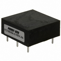
Manufacturer Part Number
FC100V5A
Description
FILTER 5 AMP PC MOUNT
Manufacturer
POWER ONE
Series
FCr
Datasheet
1.FC100V5A-G.pdf
(41 pages)
Specifications of FC100V5A
Filter Type
Power Line
Voltage - Rated
100V
Current
5A
Mounting Type
Through Hole
Termination Style
PCB Pins
Operating Temperature Min Deg. C
-40C
Operating Temperature Max Deg. C
85C
Rad Hardened
No
Lead Free Status / RoHS Status
Contains lead / RoHS non-compliant
Inductance
-
Lead Free Status / RoHS Status
Contains lead / RoHS non-compliant, Not Compliant
Other names
179-2178
Available stocks
Company
Part Number
Manufacturer
Quantity
Price

Part Number:
FC100V5A
Manufacturer:
POWER-O
Quantity:
20 000
Part Number:
FC100V5A
Quantity:
55


Printed Circuit Board Design
For optimum filtering, all shunt capacitors which are used in either the input or output circuits must be wired with "Four-
Terminal" techniques. Traces enter the node of the capacitor on one side of its pad (surface mount or discrete) and depart
from the other side. Capacitors are never "Tee'd" from other traces. The traces feeding the capacitors should be close
together and parallel. Never leave large loops in input (or output) and return traces in the printed circuit board designs for
power converters. Large loops form large antennas; large antennas create the most radiated EMI.
It is recommended that one layer of the board which carries the filter and converter(s) be dedicated as a ground plane.
Preferably, this is the layer directly under the modules. It should extend out beyond the edges of the modules. The ground
plane should be connected to earth ground, or to +Vin.
Manufacturing Issues
P
The incorporation of completed power modules into assemblies, or installation into mother boards, can be handled by the
conventional industry methods. The stanchions which are fabricated of PPS plastic, along with all the other component parts
used, will withstand normal preheat temperatures associated with standard soldering operations. The most common method
for mass soldering of the power supply to a mother board is “wave soldering” and should be profiled approximately as follows:
1. The solder pot should be set at 500 °F and the conveyor should have a speed preset to insure that each section of the
bottom side of the assembly dwells in the molten solder wave for 3 to 4 seconds. It is imperative that a correct temperature
profile be used, not only to reduce solder defects but to eliminate any chance of thermal shock on the components.
2. The motherboard should attain a top side preheat temperature of 220° to 240° F before it enters the solder wave. The
temperature change between the preheat and the soldering zones should be minimized.
3. The cooling rate after the solder wave should be similar in drop in temperature to the preheat rise.
N
MCD10059 Rev. 1.1, 21-Jan-10
ROCESSING OF
OTES ON
Power-One through-hole pins are tin/lead plated and are easily soldered if all process parameters are met. However, in
fluxing, the flux density, the activity and the ratio of flux foam to wave height must be closely monitored and controlled to
maintain minimum solder defects.
In controlling the solder profile, preheating of the assembly in two or three stages minimizes the thermal shock damage
and increases the end life of the unit.
If the power converters are to be hand soldered into the motherboard, a temperature controlled iron of 700° F (MAX) is
recommended.
While Power-One power converters generally spend about 3 seconds in the wave, they are designed to withstand
soldering temperatures of 500° F for up to 10 seconds.
If non-conventional methods are to be used to solder Power-One power supplies to the motherboard, contact Power-One
Technical Support before proceeding.
P
ROCESSING OF
C
OMPLETED
C
OMPLETED
P
OWER
M
ODULES
P
OWER
M
ODULES
F & FC Series DC-DC Converter Input Filters
FC Series, 0-100V, 5/10/20 Amps, TH Mount
Page 29 of 41
www.power-one.com
Related parts for FC100V5A
Image
Part Number
Description
Manufacturer
Datasheet
Request
R

Part Number:
Description:
SWITCHING POWER SUPPLIES, SINGLE OUTPUT, 80 WATTS
Manufacturer:
POWER ONE
Datasheet:
Part Number:
Description:
HAS SERIES - 30 WATT
Manufacturer:
POWER ONE
Datasheet:
Part Number:
Description:
SINGLE OUTPUT
Manufacturer:
POWER ONE
Datasheet:

Part Number:
Description:
BRS DC/DC converters(1.5 WATT)
Manufacturer:
Power-One
Datasheet:
Part Number:
Description:
3...15 Watt DC-DC Converter
Manufacturer:
Power-One
Datasheet:
Part Number:
Description:
HBS SERIES - 100 WATT
Manufacturer:
Power-One
Datasheet:
Part Number:
Description:
3...15 Watt DC-DC Converter
Manufacturer:
Power-One
Datasheet:
Part Number:
Description:
BUS DC/DC converters(3 WATT)
Manufacturer:
Power-One
Datasheet:
Part Number:
Description:
HES SERIES 150 WATT
Manufacturer:
Power-One
Datasheet:
Part Number:
Description:
1.25 WATT
Manufacturer:
Power-One
Datasheet: