IP4035CX24/LF/P,13 NXP Semiconductors, IP4035CX24/LF/P,13 Datasheet
IP4035CX24/LF/P,13
Specifications of IP4035CX24/LF/P,13


Related parts for IP4035CX24/LF/P,13


IP4035CX24/LF/P,13 Summary of contents
Page 1
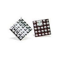
IP4035CX24 10-channel integrated filter network with ESD input protection to IEC 61000-4-2 level 4 Rev. 01 — 12 February 2010 1. Product profile 1.1 General description The IP4035CX24 is a 10-channel RC low-pass filter array which is designed to provide ...
Page 2
... NXP Semiconductors 2. Pinning information 2.1 Pinning Fig 1. 2.2 Pin description Table 1. Pin B1 and D1 A2 and D2 B2 and D3 A5 and D4 B5 and D5 C1 and E1 C2 and E2 C3 and E3 C4 and E4 C5 and E5 A3, A4, B3 IP4035CX24_1 Product data sheet 10-channel integrated filter network with ESD input protection ...
Page 3
... NXP Semiconductors 3. Ordering information Table 2. Ordering information Type number Package Name IP4035CX24 WLCSP24 4. Functional diagram Fig 2. 5. Limiting values Table 3. In accordance with the Absolute Maximum Rating System (IEC 60134). Symbol ESD tot T stg T reflow(peak) T amb Device is qualified with 1 000 pulses of ±15 kV contact discharges each, according to the IEC 61000-4-2 [1] model and far exceeds the specified level contact discharge) ...
Page 4
... NXP Semiconductors 6. Characteristics Table amb Symbol Parameter R s(ch Table amb Symbol Parameter α il α ct IP4035CX24_1 Product data sheet 10-channel integrated filter network with ESD input protection Channel characteristics ° C; unless otherwise specified. Conditions channel series resistance channel capacitance V bias(DC) breakdown voltage ...
Page 5
... NXP Semiconductors 7. Application information 7.1 Insertion loss The insertion loss measurement configuration of a typical 50 Ω NetWork Analyzer (NWA) system for evaluation of the IP4035CX24 is shown in The insertion loss of all channels for frequencies GHz is displayed in The insertion loss is measured with a test PCB utilizing laser drilled micro-via holes that connect the PCB ground plane to the IP4035CX24 ground pins ...
Page 6
... NXP Semiconductors 7.2 Crosstalk The crosstalk measurement configuration of a typical 50 Ω NWA system for evaluation of the IP4035CX24 is shown in The measured crosstalk within the IP4035CX24 Ω NWA system from one channel to another is shown in worst and the best case conditions in terms of physical distance. In both cases the signal input pin is C1. While pin E2 is very close to the input, pin E5 is relatively far away. In all cases, unused connections are terminated with 50 Ω ...
Page 7
... NXP Semiconductors 8. Package outline WLCSP24: wafer level chip-size package; 24 bumps ( A1) bump A1 index area European projection Fig 7. Package outline IP4035CX24 (WLCSP24) Table 6. Dimensions for Figure 7 Symbol IP4035CX24_1 Product data sheet 10-channel integrated filter network with ESD input protection Min Typ 0.60 0.65 ...
Page 8
... NXP Semiconductors 9. Design and assembly recommendations 9.1 PCB design guidelines For optimum performance it is recommended to use a Non-Solder Mask PCB Design (NSMD), also known as a copper-defined design, incorporating laser-drilled micro-vias connecting the ground pads to a buried ground-plane layer. This results in the lowest possible ground inductance and provides the best high frequency and ESD performance ...
Page 9
... NXP Semiconductors Table 9. Symbol T reflow(peak dT/dt 10. Abbreviations Table 10. Acronym DUT EMI ESD FR4 NSMD PCB PCS RFI RoHS WLCSP 11. Revision history Table 11. Revision history Document ID Release date IP4035CX24_1 20100212 IP4035CX24_1 Product data sheet 10-channel integrated filter network with ESD input protection ...
Page 10
... Terms and conditions of commercial sale of NXP Semiconductors. Right to make changes — NXP Semiconductors reserves the right to make changes to information published in this document, including without limitation specifications and product descriptions, at any time and without notice ...
Page 11
... NXP Semiconductors’ specifications such use shall be solely at customer’s own risk, and (c) customer fully indemnifies NXP Semiconductors for any liability, damages or failed product claims resulting from customer design and use of the product for automotive applications beyond NXP Semiconductors’ ...
Page 12
... NXP Semiconductors 14. Contents 1 Product profile . . . . . . . . . . . . . . . . . . . . . . . . . . 1 1.1 General description . . . . . . . . . . . . . . . . . . . . . 1 1.2 Features and benefits . . . . . . . . . . . . . . . . . . . . 1 1.3 Applications . . . . . . . . . . . . . . . . . . . . . . . . . . . 1 2 Pinning information . . . . . . . . . . . . . . . . . . . . . . 2 2.1 Pinning . . . . . . . . . . . . . . . . . . . . . . . . . . . . . . . 2 2.2 Pin description . . . . . . . . . . . . . . . . . . . . . . . . . 2 3 Ordering information . . . . . . . . . . . . . . . . . . . . . 3 4 Functional diagram . . . . . . . . . . . . . . . . . . . . . . 3 5 Limiting values Characteristics . . . . . . . . . . . . . . . . . . . . . . . . . . 4 7 Application information 7.1 Insertion loss . . . . . . . . . . . . . . . . . . . . . . . . . . 5 7.2 Crosstalk Package outline . . . . . . . . . . . . . . . . . . . . . . . . . 7 9 Design and assembly recommendations ...