CUB5B000 Red Lion Controls, CUB5B000 Datasheet - Page 15
CUB5B000
Manufacturer Part Number
CUB5B000
Description
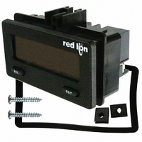
COUNTER/RATE IND DUAL RD/GN BKLT
Manufacturer
Red Lion Controls
Series
CUB5r
Type
Counter/Rate Indicatorr
Datasheet
1.CUB5RLY0.pdf
(16 pages)
Specifications of CUB5B000
Count Rate
20kHz
Number Of Digits/alpha
8
Input Type
Voltage, Switch Closure, Transistor Switch
Voltage - Supply
9 V ~ 28 V
Display Type
LCD Backlit
No. Of Digits / Alpha
8
Digit Height
11.7mm
Counting Speed
20kHz
Operating Temperature Range
-35°C To +75°C
Signal Input Type
Current
Display Mode
LCD Selectable Transmissive
Character Size
0.46"
Accuracy
±0.01% %
Connection Type
Screw
Counter Type
Electronic
Cut Out, Panel
2.68×1.3 "
Dimensions
2.95"L×1.86"W×1.54"H
Display Digit Height
0.46 "
Frequency, Operating
20 kHz (Max.)
Function
Counter/Rate Indicator
Material, Casing
Plastic
Memory Type
E2PROM
Mounting Type
Panel
Number Of Digits
8
Primary Type
Electronic
Range, Measurement
-9999999 to 999999
Special Features
Programmable
Standards
CE Approved
Temperature, Operating, Range
0 to 60 °C
Terminal Type
Screw Terminal
Termination
Screw Terminal
Voltage, Supply
9 to 28 VDC
Weight
85 g
Memory
Nonvolatile EEPROM
User Input
Programmable, Connect to Common to Activate Function
Rate Minimum Input Frequency
0.01 Hz
Rate Maximum Frequency
20 kHz
Operating Temperature
0 to 60°C
Panel Cutout
2.68" × 1.30"
Backlight Power
9-28VDC
Backlighting Color
Red Or Green
Rohs Compliant
Yes
Lead Free Status / RoHS Status
Lead free / RoHS Compliant
Output Type
-
Lead Free Status / Rohs Status
RoHS Compliant part
Other names
RLC122
Available stocks
Company
Part Number
Manufacturer
Quantity
Price
Company:

Part Number:
CUB5B000
Manufacturer:
Red Lion Controls
Quantity:
135


Abbreviated Transmission
* These characters only appear in the last line of a block print.
leaving only the numeric part of the response.
Meter Response Examples:
1. Node address = 17, full field response, Counter A = 875
2. Node address = 0, full field response, Setpoint 1 = -250.5
3. Node address = 0, abbreviated response, Setpoint 1 = 250, last line of block
Command Response Time
operation). During RS232 transmissions, the meter ignores commands while
transmitting data, but instead uses RXD as a busy signal. When sending
commands and data to the meter, a delay must be imposed before sending
another command. This allows enough time for the meter to process the
command and prepare for the next command.
string to the com port, thus initiating a transmission. During t
characters are under transmission and at the end of this period, the command
terminating character (* or $) is received by the meter. The time duration of t
is dependent on the number of characters and baud rate of the channel.
command and when complete, performs the command function. This time
interval t
to accept another command.
of the command terminating character. The ‘*’ terminating character results in a
response time of 50 msec. minimum. This allows sufficient time for the release
of the sending driver on the RS485 bus. Terminating the command line with ‘$’
results in a response time (t
this terminating character requires that sending drivers release within 2 msec.
after the terminating character is received.
character of the reply. As with t
number of characters and baud rate of the channel. At the end of t
ready to receive the next command.
times t
The abbreviated response suppresses the node address and register ID,
print
The meter can only receive data or transmit data at any one time (half-duplex
At the start of the time interval t
At the start of time interval t
If the meter is to reply with data, the time interval t
At the beginning of time interval t
The maximum serial throughput of the meter is limited to the sum of the
RESPONSE FROM METER
NO REPLY FROM METER
1
Ready
Ready
1-12
Byte
, t
17 CTA
SP1
13
14
15
16
17
2
2
varies. If no response from the meter is expected, the meter is ready
and t
t
3
t
1
= (10 times the # of characters) / baud rate
3
.
= (10 times the # of characters) / baud rate
Description
12 byte data field, 10 bytes for number, one byte for
sign, one byte for decimal point
<CR> (carriage return)
<LF> (line feed)
<SP>* (Space)
<CR>* (carriage return)
<LF>* (line feed)
Terminator
Transmission
Command
Command
Received
String
-250.5<CR><LF>
250<CR><LF><SP><CR><LF>
875 <CR><LF>
t
t
1
1
Timing Diagram Figure
2
) of 2 msec. minimum. The faster response time of
1
, the time duration of t
2
1
, the meter starts the interpretation of the
Character
Response
, the computer program prints or writes the
of Reply
Meter
Time
t
t
First
2
2
3
, the meter responds with the first
Ready
Transmission
Reply
Time
2
t
3
is controlled by the use
3
is dependent on the
1
Ready
, the command
3
, the meter is
1
15
Communication Format
In serial communications, the voltage is switched between a high and low level
at a predetermined rate (baud rate) using ASCII encoding. The receiving device
reads the voltage levels at the same intervals and then translates the switched
levels back to a character. The voltage level conventions depend on the interface
standard. The table lists the voltage levels for each standard.
characters (0 to
an optional parity bit and one or more ending stop bits. The data format and
baud rate must match that of other equipment in order for communication to
take place. The figures list the data formats employed by the meter.
Start Bit and Data Bits
receiving device to prepare for reception of data. One bit period later, the least
significant bit of the ASCII encoded character is transmitted, followed by the
remaining data bits. The receiving device then reads each bit position as they are
transmitted.
Parity Bit
a zero or a one, so that the total number of ones contained in the transmission
(including the parity bit) is either even or odd. This bit is used by the receiver to
detect errors that may occur to an odd number of bits in the transmission.
However, a single parity bit cannot detect errors that may occur to an even
number of bits. Given this limitation, the parity bit is often ignored by the
receiving device. The CUB5 meter ignores the parity bit of incoming data and
sets the parity bit to odd, even or none (mark parity) for outgoing data.
Stop Bit
period pause to allow the receiver to prepare to re-synchronize to the start of a
new transmission (start bit of next byte). The receiver then continuously looks
for the occurrence of the start bit. If 7 data bits and no parity is selected, then 2
stop bits are sent from the meter.
The Company warrants the products it manufactures against defects in materials and
workmanship for a period limited to two years from the date of shipment, provided the
products have been stored, handled, installed, and used under proper conditions. The
Company’s liability under this limited warranty shall extend only to the repair or
replacement of a defective product, at The Company’s option. The Company disclaims
all liability for any affirmation, promise or representation with respect to the products.
The customer agrees to hold Red Lion Controls harmless from, defend, and indemnify
RLC against damages, claims, and expenses arising out of subsequent sales of RLC
products or products containing components manufactured by RLC and based upon
personal injuries, deaths, property damage, lost profits, and other matters which Buyer,
its employees, or sub-contractors are or may be to any extent liable, including without
limitation penalties imposed by the Consumer Product Safety Act (P.L. 92-573) and
liability imposed upon any person pursuant to the Magnuson-Moss Warranty Act (P.L.
93-637), as now in effect or as amended hereafter.
No warranties expressed or implied are created with respect to The Company’s products
except those expressly contained herein. The Customer acknowledges the disclaimers
and limitations contained herein and relies on no other warranties or affirmations.
Data is transferred from the meter through a serial communication channel.
Data is transmitted one byte at a time with a variable idle period between
Data transmission always begins with the start bit. The start bit signals the
After the data bits, the parity bit is sent. The transmitter sets the parity bit to
The last character transmitted is the stop bit. The stop bit provides a single bit
LOGIC
* Voltage levels at the Receiver
1
0
INTERFACE STATE
space (active)
mark (idle)
). Each ASCII character is “framed” with a beginning start bit,
Character Frame Figure
LIMITED WARRANTY
TXD,RXD; +3 to +15 V
TXD,RXD; -3 to -15 V
RS232*
a-b > +200 mV
a-b < -200 mV
RS485*