CUB5B000 Red Lion Controls, CUB5B000 Datasheet - Page 8
CUB5B000
Manufacturer Part Number
CUB5B000
Description
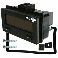
COUNTER/RATE IND DUAL RD/GN BKLT
Manufacturer
Red Lion Controls
Series
CUB5r
Type
Counter/Rate Indicatorr
Datasheet
1.CUB5RLY0.pdf
(16 pages)
Specifications of CUB5B000
Count Rate
20kHz
Number Of Digits/alpha
8
Input Type
Voltage, Switch Closure, Transistor Switch
Voltage - Supply
9 V ~ 28 V
Display Type
LCD Backlit
No. Of Digits / Alpha
8
Digit Height
11.7mm
Counting Speed
20kHz
Operating Temperature Range
-35°C To +75°C
Signal Input Type
Current
Display Mode
LCD Selectable Transmissive
Character Size
0.46"
Accuracy
±0.01% %
Connection Type
Screw
Counter Type
Electronic
Cut Out, Panel
2.68×1.3 "
Dimensions
2.95"L×1.86"W×1.54"H
Display Digit Height
0.46 "
Frequency, Operating
20 kHz (Max.)
Function
Counter/Rate Indicator
Material, Casing
Plastic
Memory Type
E2PROM
Mounting Type
Panel
Number Of Digits
8
Primary Type
Electronic
Range, Measurement
-9999999 to 999999
Special Features
Programmable
Standards
CE Approved
Temperature, Operating, Range
0 to 60 °C
Terminal Type
Screw Terminal
Termination
Screw Terminal
Voltage, Supply
9 to 28 VDC
Weight
85 g
Memory
Nonvolatile EEPROM
User Input
Programmable, Connect to Common to Activate Function
Rate Minimum Input Frequency
0.01 Hz
Rate Maximum Frequency
20 kHz
Operating Temperature
0 to 60°C
Panel Cutout
2.68" × 1.30"
Backlight Power
9-28VDC
Backlighting Color
Red Or Green
Rohs Compliant
Yes
Lead Free Status / RoHS Status
Lead free / RoHS Compliant
Output Type
-
Lead Free Status / Rohs Status
RoHS Compliant part
Other names
RLC122
Available stocks
Company
Part Number
Manufacturer
Quantity
Price
Company:

Part Number:
CUB5B000
Manufacturer:
Red Lion Controls
Quantity:
135


SCALING FOR COUNT INDICATION
display for each pulse that is input to the unit. In many applications, there will
not be a one-to-one correspondence between input pulses and display units.
Therefore, it is necessary for the CUB5 to scale or multiply the input pulses by
a scale factor to achieve the desired display units (feet, meters, gallons, etc.)
important to note that the precision of a counter application cannot be improved
by using a scale factor greater than one. To accomplish greater precision, more
pulse information must be generated per measuring unit. The following formula
is used to calculate the scale factor.
WHERE:
Desired Display Units: Count display units acquired after pulses that occurred.
Decimal Point Position:
EXAMPLE: The counter display is used to indicate the total number of feet
hundredth resolution.
frequency, Rate Enable should be set to
remaining rate parameters are not accessible. The rate value is shown with an
annunciator of “
RAtE Enb
value assigned to rate. This parameter does not affect rate scaling calculations.
RAtE dP
Number of Pulses: Number of pulses required to achieve the desired
6.2 MODULE 2 - R
The CUB5’s scale factor is factory set to 1, to provide one count on the
The Count Scale Factor Value can range from 00.0001 to 99.9999. It is
Scale Factor = Desired Display Units x Decimal Point Position
0
0.0
0.00
0.000
0.0000
0.00000
used in a process. It is necessary to know the number of pulses for the desired
units to be displayed. The decimal point is selected to show the resolution in
hundredths.
Scale Factor = Desired Display Units x Decimal Point Position
Given that 128 pulses are equal to 1 foot, display total feet with a one-
Scale Factor = 1.00 x 100
Scale Factor = 0.007812 x 100
Scale Factor = 0.7812
Module 2 is the programming for the rate parameters. For maximum input
This selects the decimal point position for the rate display and any setpoint
=
=
=
=
=
=
R
YES
” in the Display Mode.
O
128
SEL
Number of Pulses
1
10
100
1000
10000
100000
RAtE Enb
Number of Pulses
2-rAtE
display units.
RATE DECIMAL POINT
Enable
Rate
RATE ENABLE
NO
NO
0. 0
0
Rate Decimal
RAtE dP
when not in use. When set to
Point
0. 0 00
YES
0. 0 0
ATE
0. 0 0000
0. 0 000
Display Value
Rate Scaling
RAtE dSP
S
PARAMETER MENU
ETUP
NO
, the
Rate Scaling
P
RAtE INP
Input Value
8
ARAMETERS
USEr INP
USEr ASN
RAtE dSP
(maintained)
User Input performs a Reset, Inhibit or Store function on one or both counters.
*For value entry instructions, refer to selection/value entry in the Programming
Stor-rSt
d-SELECt
Prnt-r5t
rESEt-12
RAtE INP
Pro Loc
Inhibit
d-LEVEL
d-COLOr
rESEt-1
rESEt-2
Note: * indicates Edge Triggered function. Other functions are Level Active
The User Input Assignment is only active when Counter B is enabled and the
Enter the desired Rate Display Value for the Scaling Point.*
Enter the corresponding Rate Input Value for the Scaling Point.*
The Meter section.
DISPLAY
rESEt
StorE
Print
NO
Count A
Setpoint 1 and 2 Reset *
01000. 0
Program Mode Lock-out
Display Intensity Level *
001000
Update Time
Setpoint 1 Reset *
Setpoint 2 Reset *
Maintained Reset
Print and Reset *
LO-Udt
Backlight Color *
Store and Reset
Display Select *
Rate Low
Print Request
No Function
RATE SCALING DISPLAY VALUE
NO
RATE SCALING INPUT VALUE
Inhibit
Store
MODE
USER INPUT ASSIGNMENT
USER INPUT FUNCTION
(
2-rAtE
Count A
Update Time
0
0. 1
HI-Udt
Rate High
DESCRIPTION
User Input disabled.
See Programming Mode Access chart.
(Module 3)
Inhibit counting for the selected counter(s).
Level active reset of the selected counter(s).
Freeze display of selected counter(s) while
allowing counts to accumulate internally.
Edge triggered reset of the selected
counter(s) after storing the count.
Advance once for each activation
Increase intensity one level for each
activation. (backlight version only)
Change backlight color with each activation
(backlight version only)
Serial transmit of the active parameters
selected in the Print Options (Module 5)
Same as Print Request followed by a
momentary reset of the selected counter(s).
Reset Setpoint 1 output
Reset Setpoint 2 output
Reset Setpoint 1 and 2 outputs
to
to
)
999999
99999. 9
Count b
Pro
both A-b