H7CX-A114D1 DC12-24/AC24 Omron, H7CX-A114D1 DC12-24/AC24 Datasheet - Page 2
H7CX-A114D1 DC12-24/AC24
Manufacturer Part Number
H7CX-A114D1 DC12-24/AC24
Description
COUNTER 11-PIN 12VDC 4DIGIT SPDT
Manufacturer
Omron
Series
H7CXr
Datasheet
1.H7CX-AS_AC100-240.pdf
(63 pages)
Specifications of H7CX-A114D1 DC12-24/AC24
Count Rate
*
Number Of Digits/alpha
6
Input Type
*
Output Type
*
Voltage - Supply
12 V ~ 24 VDC, 24VAC
Display Type
*
No. Of Digits / Alpha
4
Meter Function
Counter
Signal Input Type
PNP/NPN
Supply Voltage Max
24VDC
Character Size
11.5mm
Ip/nema Rating
IP66 / NEMA 4
Panel Cutout Height
45mm
Supply Voltage Min
12VDC
Lead Free Status / RoHS Status
Lead free / RoHS Compliant
Other names
H7CX-A114D1DC12-24/AC24
H7CXA114D1DC1224AC24
H7CXA114D1DC1224AC24


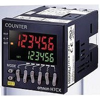
DIN 48 × 48 mm Multifunction Preset Counter
with a Bright, Easy-to-view, Negative
Transmissive LCD
• Programmable PV color to visually alert when output status
• Configurable as 1-stage counter, 2-stage counter, total and pre-
• Meets a variety of mounting requirements:
• Six-language instruction manual.
changes (screw terminal block models).
set counter, batch counter, dual counter, or tachometer. (Config-
urability varies with model.)
Screw terminal block models, and pin-style terminal models.
Multifunction Preset Counter
H7CX-A
Model Number Structure.............................................................. 3
Ordering Information.................................................................... 3
Specifications............................................................................... 4
Connections................................................................................. 8
Nomenclature .............................................................................. 12
Dimensions .................................................................................. 13
Operating Procedures.................................................................. 17
Additional Information .................................................................. 37
Setting Procedure Guide ....................................................... 17
Operating Procedures (Counter Function) ............................ 18
Operating Procedures (Tachometer Function) ...................... 30
Operation in Configuration Selection Mode........................... 36
Contents
2