H7CX-AWSD DC12-24 Omron, H7CX-AWSD DC12-24 Datasheet - Page 36
H7CX-AWSD DC12-24
Manufacturer Part Number
H7CX-AWSD DC12-24
Description
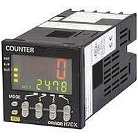
COUNTER SCREW-TERM 6DIGT 1/16DIN
Manufacturer
Omron
Series
H7CXr
Datasheet
1.H7CX-AS_AC100-240.pdf
(63 pages)
Specifications of H7CX-AWSD DC12-24
Count Rate
*
Number Of Digits/alpha
6
Input Type
*
Output Type
*
Voltage - Supply
12 V ~ 24 V
Display Type
*
No. Of Digits / Alpha
6
Signal Input Type
PNP/NPN
Supply Voltage Max
24V
Panel Cutout Height
48mm
Supply Voltage Min
12V
Panel Cutout Width
48mm
Connector Type
Screw Terminal
Counter Supply Voltage
12-24VDC
Lead Free Status / RoHS Status
Lead free / RoHS Compliant
Lead Free Status / RoHS Status
Lead free / RoHS Compliant
Other names
H7CX-AWSDDC12-24
H7CXAWSDDC1224
H7CXAWSDDC1224


■ Operation in Configuration Selection Mode
Select which H7CX configuration is used (i.e., 1-stage counter, 2-stage counter, total and preset counter, batch counter, dual counter, or tachom-
eter) in configuration selection mode. The H7CX is also equipped with a DIP switch monitor function, a convenient function that enables the settings
of the DIP switch pins to be confirmed using the front display.
Note: 1. When the mode is changed to configuration selection mode, the present value is reset, outputs turns OFF, and counting (measuring)
2. Setting changes made in configuration selection mode are enabled when the mode is changed to run mode. If the configuration is
stops.
changed, the set value (or set value 1 and set value 2), OUT1 set value or OUT2 set value are initialized.
(See note 2.)
Counting stopped
Counting possible
Power ON
1 s min.
+
1
(See note 1.)
Configuration
selection
DIP switch
monitor
OFF
ON
To change the mode to configuration selection mode, press
the
mode will not change if the
Select the configuration using the
models)
The H7CX is factory-set to the 1-stage counter configuration (2-stage
counter configuration with H7CX-AW@/-A4W@ models).
The configuration that can be selected depend on the model.
The status of the DIP switch pins (1 to 8) can be confirmed using the
Note: This display is possible only if DIP switch pin 1 (DIP switch
(1-stage counter) (2-stage counter)
Example
settings) is set to ON (i.e., enabled).
1
keys.
Key for 1 s min. with the
1
2
3
4
5
(Total and preset
counter)
6
1
7
key is pressed first.
8
key held down. The
1
keys. (
(Batch counter)
Indicates that DIP switch pin 8 is ON.
Indicates that DIP switch pin 7 is OFF.
Indicates that DIP switch pin 6 is ON.
Indicates that DIP switch pin 5 is OFF.
Indicates that DIP switch pin 4 is ON.
Indicates that DIP switch pin 3 is OFF.
Indicates that DIP switch pin 2 is ON.
Indicates that DIP switch pin 1 is ON.
key only for 6-digit
(Dual counter)
(Tachometer)
H7CX-A
1
36