PAXLVD00 Red Lion Controls, PAXLVD00 Datasheet - Page 3
PAXLVD00
Manufacturer Part Number
PAXLVD00
Description
VOLTMETER DC 3 1/2-DIGIT
Manufacturer
Red Lion Controls
Series
PAX®LITEr
Type
Voltmeterr
Datasheet
1.PAXLVD00.pdf
(8 pages)
Specifications of PAXLVD00
Measuring Range
0 ~ 300V
Display Style
Red Characters, Black Background
Display Type
LED
Display Face Size
3.80" L x 1.95" W (96.5 x 49.5mm)
Display Digits
3.5
Display Digits - Height
0.560" (14.22mm)
Backlight
Without
Mounting Type
Panel Mount
Termination
Terminal Block
Voltage - Supply
115VAC,230 VAC
No. Of Digits / Alpha
3-1/2
Meter Function
DC Voltmeter
Meter Range
1.999V To 300V
Digit Height
14.2mm
Power Consumption
6VA
Operating Temperature Range
0°C To +60°C
Supply Voltage Ac, Min
115V
Accuracy
±0.1% %
Connection Type
Cage-Clamp
Cut Out, Panel
3.62×1.77 "
Dimensions
4.2"L×3.8"W×1.95"H
Display Digit Height
0.56 "
Display Resolution
1 mV to 1 V
Function
Voltage
Meter Type
Panel
Number Of Digits
3-1/2
Primary Type
Electronic
Range, Measurement
1.999 to 300 VDC
Special Features
Multi-Range Unit
Standards
CE Marked, cUL Recognized
Temperature, Operating
0 to 60 °C
Voltage, Input
1.999 to 300 V
Voltage, Supply
115/230 VAC
Character Size
0.56"
Display Font Color
Red
Rohs Compliant
Yes
Lead Free Status / RoHS Status
Lead free / RoHS Compliant
Lead Free Status / RoHS Status
Lead free / RoHS Compliant, Lead free / RoHS Compliant
Other names
RLC107
Available stocks
Company
Part Number
Manufacturer
Quantity
Price
Company:

Part Number:
PAXLVD00
Manufacturer:
Red Lion Controls
Quantity:
135


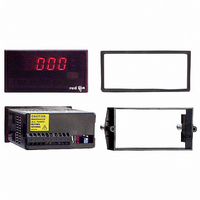
UNITS LABEL KIT (PAXLBK)
using the Units Label Kit. The backlight is controlled by a DIP switch.
1. DISPLAY: 3 1/2-digit, 0.56" (14.2 mm) high, 7-segment red LED, (-) minus
2. POWER: 115/230 VAC, switch selectable. Allowable power line variation
3. INPUT RANGES/RESOLUTION: (Selectable by jumper connections.):
4. ACCURACY:
5. OVER-RANGE INDICATION: on all modes is indicated by blanking 3
6. MAX. VOLTAGE ON LOWEST INPUT RANGE: 75 VAC or DC (Both
7. MAX. VOLTAGE ON TERMINAL BLOCK: 300 VAC or DC (Both
8. MAX. CURRENTS (FOR CURRENT METERS):
9. TEMPERATURE COEFFICIENTS:
10. ENVIRONMENTAL CONDITIONS:
G
A
AC Voltmeters
0-1.999 V/1 mV
0-19.99 V/10 mV
0-199.9 V/100 mV
0-300 V/1 V
Each meter has a units indicator with backlighting that can be customized
sign displayed when current or voltage is negative. Decimal points inserted
before 1st, 2nd, or 3rd least significant digits by DIP switch selection.
±10%, 50/60 Hz, 6 VA.
Isolation: 2300 Vrms for 1 min. between input and supply
Working Voltage: 300 V max. , CAT II
Input Impedance:
Working Voltage: 300 V max., CAT II
AC Voltmeters: ±(0.1% of Reading + 3 digits) (45-500 Hz)
AC Current Meters (45-500 Hz):
DC Voltmeters: ±(0.1% of Reading + 1 digit)
DC Current Meters:
least significant digits.
voltmeters and current meters).
voltmeters and current meters).
199.9 μA through 19.99 mA: 10 times max. range current
199.9 mA: 1 A
1.999 A: 3 A
Caution: In circuits where fault currents can exceed the maximum shunt
Operating Temperature: 0° to 60 °C
Storage Temperature: -40° to 80 °C
Voltage: All ranges1M
Current: 199.9 μA
199.9 μA/199.9 mV, 1.999 mA, 19.99 mA: ±(0.1% of Reading + 3 digits)
199.9 mA: ±(0.15% of Reading + 3 digits)
1 A: ±(0.5% of Reading + 3 digits)
199.9 μA/199.9 mV, 1.999 mA, 19.99 mA: ±(0.1% of Reading + 1 digit)
199.9 mA: ±(0.15% of Reading + 1 digit)
1.999 A: ±(0.5% of Reading + 1 digit)
Note: Any individual range may be recalibrated (scaled) to 0.1% accuracy
current, a fast-blow fuse should be installed in series with the input signal.
Otherwise, a slow blow 10 amp fuse is recommended that will allow for
start-up over current situations, while still protecting the instrument.
CCESSORIES
ENERAL
with appropriate calibration equipment.
DC:
AC:
Current meters
1.999 mA
19.99 mA
199.9 mA
1.999 A
100 PPM/
200 PPM/
AC Current Meters
0-199.9 μA/0.1 μA
0-1.999 mA/1 μA
0-19.99 mA/10 μA
0-199.9 mA/100 μA
0-1.999 A/1 mA
0-199.9 mV/100 μV
°
°
C
C
1000.1 K
100.1
10.1
M
1.1
0.1
DC:
AC:
ETER
DC Voltmeters
1.999 V/1 mV
19.99 V/10 mV
199.9 V/100 mV
300 V/1 V
Voltmeters
150 PPM/
75 PPM/
°
C
°
C
DC Current Meters
199.9 μA/0.1 μA
1.999 mA/1 μA
19.99 mA/10 μA
199.9 mA/100 μA
1.999 A/1 mA
199.9 mV/100 μV
S
PECIFICATIONS
3
11. RESPONSE TIME TO STEP CHANGE INPUT: 1 sec. nominal
12. READING RATE: 2.5 readings/sec., nominal
13. NORMAL MODE REJECTION: 50 dB 50/60 Hz (DC units only)
14. COMMON MODE REJECTION: 110 dB DC or 50/60 Hz (DC units only)
15. COMMON MODE VOLTAGE (COMM. TO EARTH): 350 volt peak
16. CERTIFICATIONS AND COMPLIANCES:
Notes:
17. CONNECTIONS: High compression cage-clamp terminal block
18. CONSTRUCTION: This unit is rated for NEMA 4X/IP65 outdoor use.
19. WEIGHT: 0.65 lbs. (0.24 Kg)
EXTERNAL CURRENT SHUNTS (APSCM)
APSCM010 current shunt converts a maximum 10 ADC signal into 100.0 mV.
The APSCM100 current shunt converts a maximum 100 ADC signal into 100.0
mV. The continuous current through the shunt is limited to 115% of the rating.
Operating and Storage Humidity: 85% max. relative humidity (non-
Vibration According to IEC 68-2-6: Operational 5 to 150 Hz, in X, Y, Z
Shock According to IEC 68-2-27: Operational 30 g, 11 msec in 3 directions.
Altitude: Up to 2000 meters
SAFETY
ELECTROMAGNETIC COMPATIBILITY:
Emissions and Immunity to EN 61326: Electrical Equipment for Measurement,
Control and Laboratory use.
1. Criterion A: Normal operation within specified limits.
2. Criterion B: Temporary loss of performance from which the unit self-
Wire Strip Length: 0.3" (7.5 mm)
Wire Gage: 30-14 AWG copper wire
Torque: 4.5 inch-lbs (0.51 N-m) max.
Installation Category II, Pollution Degree 2. One piece bezel/case. Flame
resistant. Panel gasket and mounting clip included.
To measure DC current signals greater than 2 ADC, a shunt must be used. The
Immunity to Industrial Locations:
Electrostatic discharge
Electromagnetic RF fields
Fast transients (burst)
Surge
RF conducted interference
Voltage dip/interruptions
Emissions:
Emissions
condensing)
direction for 1.5 hours, 2g.
UL Recognized Component, File #E179259, UL61010A-1, CSA C22.2
No. 61010-1
UL Listed, File #E137808, UL508, CSA C22.2 No. 14-M95
IECEE CB Scheme Test Report #04ME11209-20041018
recovers.
Recognized to U.S. and Canadian requirements under the Component
Recognition Program of Underwriters Laboratories, Inc.
LISTED by Und. Lab. Inc. to U.S. and Canadian safety standards
Type 4X Enclosure rating (Face only), UL50
IEC 61010-1, EN 61010-1: Safety requirements for electrical equipment
IP65 Enclosure rating (Face only), IEC 529
Issued by Underwriters Laboratories, Inc.
for measurement, control, and laboratory use, Part 1.
EN 61000-4-2
EN 61000-4-3
EN 61000-4-4
EN 61000-4-5
EN 61000-4-6
EN 61000-4-11
EN 55011
Criterion A
4 kV contact discharge
8 kV air discharge
Criterion B
10 V/m
Criterion B
2 kV power
2 kV signal
Criterion A
1 kV L-L,
2 kV L&N-E power
Criterion A
3 V/rms
Criterion A
0.5 cycle; 40 % variation
Class B