PAXLCL00 Red Lion Controls, PAXLCL00 Datasheet - Page 5
PAXLCL00
Manufacturer Part Number
PAXLCL00
Description
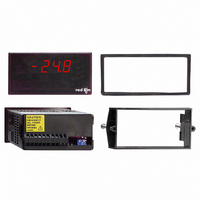
METER CURRENT LOOP 3 1/2-DIGIT
Manufacturer
Red Lion Controls
Series
PAX®LITEr
Type
Process Meter (4-20mA Loop)r
Specifications of PAXLCL00
Measuring Range
4-20mA Loop
Display Style
Red Characters, Black Background
Display Type
LED
Display Face Size
3.80" L x 1.95" W (96.5 x 49.5mm)
Display Digits
3.5
Display Digits - Height
0.560" (14.22mm)
Backlight
Without
Mounting Type
Panel Mount
Termination
Terminal Block
Voltage - Supply
85 V ~ 250 VAC
No. Of Digits / Alpha
3-1/2
Meter Function
Loop Current
Meter Range
4mA To 20mA / 10mA To 50mA
Digit Height
14.2mm
Power Consumption
6VA
Operating Temperature Range
0°C To +60°C
Supply Voltage Ac, Min
85V
Accuracy
±0.05% %
Connection Type
Cage-Clamp
Cut Out, Panel
3.62×1.77 "
Dimensions
4.2"L×3.8"W×1.95"H
Display Digit Height
0.56 "
Function
Ammeter
Number Of Digits
3-1/2
Primary Type
Electronic
Range, Measurement
4 to 20/10 to 50 mA
Special Features
Multi-Range Unit
Standards
cULus Listed, CE Marked
Temperature, Operating
0 to 60 °C
Time, Response
1 Second to settle for step change
Voltage, Supply
85 to 250 VAC
Weight
0.65 lbs
Character Size
0.56"
Rohs Compliant
NA
Lead Free Status / RoHS Status
Lead free / RoHS Compliant
Lead Free Status / RoHS Status
na, Lead free / RoHS Compliant
Other names
RLC112


EMC INSTALLATION GUIDELINES
Magnetic Interference (EMI), proper installation and wiring methods must be
followed to ensure compatibility in each application. The type of the electrical
noise, its source or the method of coupling into the unit may be different for
various installations. Listed below are some EMC guidelines for successful
installation in an industrial environment.
1. The meter should be mounted in a metal enclosure, which is properly
2. Never run Signal or Control cables in the same conduit or raceway with AC
3. Signal or Control cables within an enclosure should be routed as far away as
4. In extremely high EMI environments, the use of external EMI suppression
3.1 POWER WIRING
3.2 INPUT SIGNAL WIRING
2-WIRE, EXTERNAL EXCITATION
NOTES
1. When shielded wire leads are used, connect the shield to earth ground at the meter and insulate the other end to avoid contact with machine ground.
2. Never run signal leads in conduit, bundles, or race ways with power conductors. Avoid runs close to contactors, relays, solenoids, transformers, and other potential
Although this meter is designed with a high degree of immunity to Electro-
connected to protective earth.
power lines, conductors feeding motors, solenoids, SCR controls, and
heaters, etc. The cables should be run in metal conduit that is properly
grounded. This is especially useful in applications where cable runs are long
and portable two-way radios are used in close proximity or if the installation
is near a commercial radio transmitter.
possible from contactors, control relays, transformers, and other noisy
components.
devices, such as ferrite suppression cores, is effective. Install them on Signal
and Control cables as close to the unit as possible. Loop the cable through the
core several times or use multiple cores on each cable for additional protection.
AC Power
Terminal 1: VAC
Terminal 2: VAC
sources of electrical noise.
K1
K1
PAXLCL
PAXLCL
10-50MA
10-50MA
4-20MA
4-20MA
-LOOP
-LOOP
+LOOP
-LOOP
-LOOP
+LOOP
10-50mA
5
4
3
2
4-20mA
5
4
3
2
1
1
115/230
1
EXTERNAL LOOP
POWER SUPPLY
EXTERNAL LOOP
POWER SUPPLY
(+)
(+)
2
10-50MA
4-20MA
XDUCER
XDUCER
(+)
(+)
(-)
(-)
2-WIRE, WITH EXCITATION (Series Conn.) 2-WIRE, WITH EXCITATION (Parallel Conn.)
EXCITATION
EXCITATION
AT 50mA
K1
K1
AT 50mA
24 VDC
SUPPLY
SUPPLY
24 VDC
PAXLCL
PAXLCL
10-50MA
10-50MA
4-20MA
4-20MA
-LOOP
-LOOP
+LOOP
-LOOP
-LOOP
+LOOP
(-)
(+)
(-)
(+)
10-50mA
7
6
5
4
3
2
4-20mA
7
6
5
4
3
2
1
1
5
5. Long cable runs are more susceptible to EMI pickup than short cable runs.
6. Switching of inductive loads produces high EMI. Use of snubbers across
Install line filters on the power input cable to the unit to suppress power line
interference. Install them near the power entry point of the enclosure. The
following EMI suppression devices (or equivalent) are recommended:
Therefore, keep cable runs as short as possible.
inductive loads suppresses EMI.
Ferrite Suppression Cores for signal and control cables:
Line Filters for input power cables:
Note: Reference manufacturer’s instructions when installing a line filter.
Snubber: RLC#SNUB0000.
Fair-Rite # 0443167251 (RLC #FCOR0000)
TDK # ZCAT3035-1330A
Steward #28B2029-0A0
Schaffner # FN610-1/07 (RLC #LFIL0000)
Schaffner # FN670-1.8/07
Corcom #1VR3
10-50MA
4-20MA
XDUCER
XDUCER
(+)
(+)
(-)
(-)
EXCITATION
EXCITATION
AT 50mA
K1
AT 50mA
K1
24 VDC
SUPPLY
24 VDC
SUPPLY
PAXLCL
PAXLCL
10-50MA
10-50MA
4-20MA
4-20MA
-LOOP
-LOOP
+LOOP
-LOOP
-LOOP
+LOOP
(-)
(+)
(-)
(+)
10-50mA
4
4-20mA
4
7
6
5
3
2
1
7
6
5
3
2
1
EXCITATION
EXCITATION
(+)
(+)
10-50MA
4-20MA
XDUCER
XDUCER
(+)
(-)
(+)
(-)