PAXLCL00 Red Lion Controls, PAXLCL00 Datasheet - Page 6
PAXLCL00
Manufacturer Part Number
PAXLCL00
Description
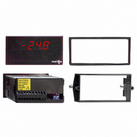
METER CURRENT LOOP 3 1/2-DIGIT
Manufacturer
Red Lion Controls
Series
PAX®LITEr
Type
Process Meter (4-20mA Loop)r
Specifications of PAXLCL00
Measuring Range
4-20mA Loop
Display Style
Red Characters, Black Background
Display Type
LED
Display Face Size
3.80" L x 1.95" W (96.5 x 49.5mm)
Display Digits
3.5
Display Digits - Height
0.560" (14.22mm)
Backlight
Without
Mounting Type
Panel Mount
Termination
Terminal Block
Voltage - Supply
85 V ~ 250 VAC
No. Of Digits / Alpha
3-1/2
Meter Function
Loop Current
Meter Range
4mA To 20mA / 10mA To 50mA
Digit Height
14.2mm
Power Consumption
6VA
Operating Temperature Range
0°C To +60°C
Supply Voltage Ac, Min
85V
Accuracy
±0.05% %
Connection Type
Cage-Clamp
Cut Out, Panel
3.62×1.77 "
Dimensions
4.2"L×3.8"W×1.95"H
Display Digit Height
0.56 "
Function
Ammeter
Number Of Digits
3-1/2
Primary Type
Electronic
Range, Measurement
4 to 20/10 to 50 mA
Special Features
Multi-Range Unit
Standards
cULus Listed, CE Marked
Temperature, Operating
0 to 60 °C
Time, Response
1 Second to settle for step change
Voltage, Supply
85 to 250 VAC
Weight
0.65 lbs
Character Size
0.56"
Rohs Compliant
NA
Lead Free Status / RoHS Status
Lead free / RoHS Compliant
Lead Free Status / RoHS Status
na, Lead free / RoHS Compliant
Other names
RLC112


DESCRIPTION OF OPERATION
with an analog scaling circuit (shown above). The unit was designed primarily for
use with 4-20 mA and 10-50 mA current loop signal circuits. However, it can also
be adapted to other current ranges, such as 0-50 mA, 0-20 mA, 0-10 mA, and in
a great many applications it can be used even with 0-5 mA and 1-5 mA current
loops. In addition, input current can be reversed in polarity resulting in negative
numerical readout with a minus (-) sign displayed. Input terminals 3 and 4 are
connected in series with 10-50 mA current loops, and Terminal 3 and 5 are series
connected with 4-20 mA loops. In either case, the voltage drop generated across
the shunt resistor(s) ranges from approximately 0.12 V min. (@ 4 or 10 mA) to
0.59 V max. (@ 20 or 50 mA). The buffer amplifier (K1) conditions and filters
the input signal voltage and applies it to the input of the scaling circuit. The
procedure for scaling PAX Lite Current Loop Meters is simplified by dividing the
scaling process into two separate components, span adjustments and offset
adjustments which are defined in the following discussion.
SPAN ADJUSTMENTS
decimal points, when the input signal current is varied from minimum (4 or 10
mA) to maximum (20 or 50 mA). For example, if a unit is to display 25.0 @ 4
mA and 100.0 @ 20 mA, the span is 750 (the difference between 250 and 1000).
Had the minimum display been -25.0 @ 4 mA and +100.0 @ 20 mA, the span
would be 1250 (1000 - (-250) = 1250). (Note: the terms “GAIN”, “SCALE”, and
“SENSITIVITY” are also frequently used interchangeably with the term
“SPAN.”) The PAX Lite Current Loop Meter
can be set up over a very wide span range by
means of the coarse DIP switches S6-S10,
and the fine screwdriver adjustment pot,
located at the back cover. The coarse span
switches add parallel input resistors to the
summing amplifier (K2), thereby increasing
its gain, or sensitivity, as more summing
resistors are added. Effectively, adding more
parallel input resistors, increases the slope of
the transfer curve (at right) and increases the
numerical readout for a given input signal
current change. The input summing resistor values are weighted in a binary
progression, so they can be switched in combinations to give 32 discrete steps of
span. The fine adjust control brackets these coarse steps and can be adjusted to the
exact span needed.
4.0 S
The PAX Lite Current Loop Meter consists of a digital volt meter combined
Span is defined as the numerical range that the display traverses, disregarding
(-)
4-20MA
RANGE
(-)
10-50MA
RANGE
(+)
5
4
3
CALING THE
-LOOP
-LOOP
+LOOP
V
I
RESISTORS
CURRENT
SHUNT
BUFFER
K2
AMP
SPAN=150
SPAN=0
V
I
+1999
+1500
+1000
INPUT SIGNAL SCALING CIRCUIT
+500
-500
0
S6
S7
S8
S9
S10
FINE SPAN ADJ.
Span Adjustment
4
INPUT SIGNAL CURRENT
M
SPAN ADJUST
8
2100
1050
525
260
130
12
ETER
16
16R
12R
PAXLCL SCHEMATIC
2R
4R
8R
SUBTRACT
R
20
S5
(-)
+V
R
5.5K
S4 S3 S2
K2
-V R
S1
OFFSET
DIRECTION
SWITCH
(+)
ADD
6
These values are based on the standard current-loop spans of 4 to 20 mA (16 mA
current variation) and 10-50 mA (40 mA current variation). In other words, if S7
only is turned “ON”, the numerical readout will display a change approximately
1050 for a current swing of 16 mA (4-20 mA input) or 40 mA (10-50 mA input).
If S8 were also turned “ON”, the numerical readout would swing approximately
1575 (1050 for S7 + 525 for S8) for the same signal current variation. The fine
control has a continuous span range of approximately 0-150.
OFFSET ADJUSTMENTS
“ZERO-BASED”, i.e., the numerical readout displays “0” when the signal
current goes to zero. With current loop ranges such as 0-5 or 0-10, or 0-20 mA,
and with Bi-Polar (+/-) signals, this is often the desired condition. However,
with 4-20 and 10-50 mA current loops, the minimum current level of 4 or 10
mA usually represents the zero level of the parameter being displayed. There are
also many applications where the
minimum (or zero level) represents some
value that does not fall on a zero based
transfer curve. To accommodate non-zero
based applications, the PAX Lite Current
Loop Meter has provisions for offsetting
the transfer curve over a wide range.
Essentially, offset moves the transfer
curve up or down to change its intercept
with the numerical readout axis, but it
does not change the slope (SPAN) of the
transfer curve. In the PAX Lite Current
Loop Meter, offset is accomplished by
adding (or subtracting) a constant at the input of the summing amplifier (K2).
This offset constant is summed in with a switched binary resistor network and
a fine adjust offset control in a similar manner to that used for span adjustment.
Switches S2-S5 can be turned on in combinations to give 16 different coarse
offset levels. Each switch is labeled to show the approximate amount of offset
contributed when it is turned “ON”. Switch 1 selects the polarity of the
switched-in offset value and allows offsetting the transfer curve “UP” (adding
the offset constant) or “DOWN” (subtracting). The fine offset control has a
numerical readout range of ±100 and brackets all the coarse switched ranges.
The approximate span contributed by each switch is shown on the rear label.
In the foregoing discussion of span, the transfer curves were shown as
FINE
OFFSET
ADJUST
V
O
DIGITAL DISPLAY
VOLTMETER
CIRCUIT
A/D
DIGITAL VOLTMETER
mA
SWITCHES
DECIMAL
POINT
S3 S2 S1
+1500
+1000
+1999
+500
-500
0
Offset Adjustment
INPUT SIGNAL CURRENT
4
8
S4
12
ANNUNCIATOR
BACKLIGHT
SWITCH
16
20