PAXI0000 Red Lion Controls, PAXI0000 Datasheet - Page 11
PAXI0000
Manufacturer Part Number
PAXI0000
Description
1/8 DIN DIGITAL INPUT PANEL METE
Manufacturer
Red Lion Controls
Series
PAXr
Type
Multimeterr
Specifications of PAXI0000
Display Style
Red Characters, Black Background
Display Type
LED
Display Face Size
3.80" L x 1.95" W (96.5 x 49.5mm)
Display Digits
6
Display Digits - Height
0.560" (14.22mm)
Mounting Type
Panel Mount
Termination
Terminal Block
Voltage - Supply
85 ~ 250VAC
No. Of Digits / Alpha
6
Signal Input Type
Pulse
Character Size
0.56"
Ip/nema Rating
IP65 / NEMA 4X
Panel Cutout Height
1.77"
Display Font Color
Red
Panel Cutout Width
3.62"
Accuracy
±0.01% %
Connection Type
Cage-Clamp
Cut Out, Panel
1/8 DIN
Digit Height
0.56
Dimensions
4.2"L×3.8"W×1.95"H
Display Digit Height
0.56 "
Function
Counter/Rate Indicator
Indicator Type
Counter/Rate Indicator
Number Of Digits
5
Primary Type
Electronic
Range, Measurement
±99999999
Special Features
Programmable Function Keys
Temperature, Operating, Range
0 to 50 °C
Voltage, Supply
85 to 250 VAC
Counter Supply Voltage
85-250VAC
Rohs Compliant
Yes
Lead Free Status / RoHS Status
Lead free / RoHS Compliant
Backlight
-
Measuring Range
-
Lead Free Status / Rohs Status
RoHS Compliant part
Other names
Q4600348


4.5 PAXI SERIAL COMMUNICATION WIRING
RS232 Communications
50 feet. Data Terminal Equipment (DTE) transmits data on the Transmitted Data
(TXD) line and receives data on the Received Data (RXD) line. Data Computer
Equipment (DCE) receives data on the TXD line and transmits data on the RXD
line. The PAX emulates a DTE. If the other device connected to the meter also
emulates a DTE, the TXD and RXD lines must be interchanged for
communications to take place. This is known as a null modem connection. Most
printers emulate a DCE device while most computers emulate a DTE device.
without a pause in between. In these cases, the meter employs a busy function.
determine if the receiving device is “busy”. The receiving device asserts that it
is busy by setting the RXD line to a space condition (logic 0). The meter then
suspends transmission until the RXD line is released by the receiving device.
4.6 PAXI ANALOG OUTPUT WIRING
5.0 R
PAX METER (DTE)
RS232 is intended to allow two devices to communicate over distances up to
Some devices cannot accept more than two or three characters in succession
As the meter begins to transmit data, the RXD line (RS232) is monitored to
ANALOG OPTION CARD FIELD TERMINALS
16
17
18
19
** Factory setting for the F1, and F2 keys is NO mode.
*** Factory setting for the RST key is
* Counters B, and C are locked out in Factory Settings (PAXC and PAXI only).
+
-
+
-
KEY
DSP
PAR
F1
F2
RST
FEMALE
9
6
Extended Comms Connection Figure
OUTPUT
OUTPUT
0-10V
ANALOG
0-20mA
ANALOG
Terminal Block Connection Figure
5
1
EVIEWING THE
DISPLAY MODE OPERATION
Index display through the selected displays.
Access Programming Mode
Function key 1; hold for 3 seconds for Second Function 1 **
Function key 2; hold for 3 seconds for Second Function 2 **
Reset (Function key) ***
12
13
14
15
TXD
RXD
COMM.
NC
RXD
TXD
Counter
Readout
Legends*
PIN 2 TXD
PIN 3 RXD
PIN 5 COMMON
(Reset Display).
RECEIVING DEVICE
DB25
DCE
2
3
5
A
C
B
DB25
DTE
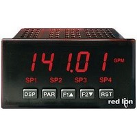
8. 8 . 8 . 8 . 8 . 8
SP1
3
2
7
DSP
F
PAR
DTE
DB9
RONT
SP2
2
3
5
F1
SP3
11
F2
4.7 PAXI PRESCALER OUTPUT WIRING
RS485 Communications
devices on a single pair of wires, distances up to 4,000 ft. and data rates as high
as 10M baud (the PAX is limited to 19.2k baud). The same pair of wires is used
to both transmit and receive data. RS485 is therefore always half-duplex, that
is, data cannot be received and transmitted simultaneously.
SP4
RST
The RS485 communication standard allows the connection of up to 32
B
PAX CONNECTOR
UTTONS AND
PROGRAMMING MODE OPERATION
Quit programming and return to Display Mode
Store selected parameter and index to next parameter
Increment selected parameter value or selections
Decrement selected parameter value or selections
Advances digit location in parameter values
Transmit
Transmit
Enable
Enable
2
3
4
Setpoint Alarm
Annunciators
Terminal Block Connection Figure
5
Extended Comms Connection Figure
PAX METER
PAX METER
+5V
+5V
33K
33K
33K
33K
12
12
13
13
14
14
15
15
B(
A(+)
NC
NC
COMM.
COMM.
(+)
-
)
*
RECEIVING DEVICE
RECEIVING DEVICE
D
* OPTIONAL
OPTIONAL
ISPLAY