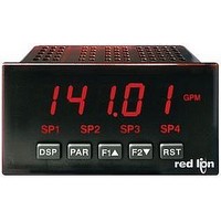
PAXI0000 Red Lion Controls, PAXI0000 Datasheet - Page 21

PAXI0000
Manufacturer Part Number
PAXI0000
Description
1/8 DIN DIGITAL INPUT PANEL METE
Manufacturer
Red Lion Controls
Series
PAXr
Type
Multimeterr
Specifications of PAXI0000
Display Style
Red Characters, Black Background
Display Type
LED
Display Face Size
3.80" L x 1.95" W (96.5 x 49.5mm)
Display Digits
6
Display Digits - Height
0.560" (14.22mm)
Mounting Type
Panel Mount
Termination
Terminal Block
Voltage - Supply
85 ~ 250VAC
No. Of Digits / Alpha
6
Signal Input Type
Pulse
Character Size
0.56"
Ip/nema Rating
IP65 / NEMA 4X
Panel Cutout Height
1.77"
Display Font Color
Red
Panel Cutout Width
3.62"
Accuracy
±0.01% %
Connection Type
Cage-Clamp
Cut Out, Panel
1/8 DIN
Digit Height
0.56
Dimensions
4.2"L×3.8"W×1.95"H
Display Digit Height
0.56 "
Function
Counter/Rate Indicator
Indicator Type
Counter/Rate Indicator
Number Of Digits
5
Primary Type
Electronic
Range, Measurement
±99999999
Special Features
Programmable Function Keys
Temperature, Operating, Range
0 to 50 °C
Voltage, Supply
85 to 250 VAC
Counter Supply Voltage
85-250VAC
Rohs Compliant
Yes
Lead Free Status / RoHS Status
Lead free / RoHS Compliant
Backlight
-
Measuring Range
-
Lead Free Status / Rohs Status
RoHS Compliant part
Other names
Q4600348
“
the chosen setpoint is programmed, the display will default to
the next setpoint to be programmed and continue the sequence for each setpoint.
Pressing PAR at
the corresponding setpoint annunciator of an “on” alarm output. Reverse (
displays the corresponding setpoint annunciator of an “off” alarm output.
“on” alarm output.
6.6 MODULE 6 - S
” in the following parameters will reflect the chosen setpoint number.) After
Select a setpoint (alarm output) to open the remaining module menu. (The
PAR
disables the display of the setpoint annunciator. Normal (
flashes the display and the corresponding setpoint annunciator of an
6-SPt
Setpoint
SPSEL
Select
PAR
Operation
PARAMETER
Standby
Stb-n
be installed into the PAX (see Ordering Information). Depending on the card installed, there will be two or four setpoint outputs
available. This section replaces the bulletin that comes with the setpoint plug-in card. Please discard the separate literature when using
the Plug-in card with the Digital PAX. For maximum input frequency, unused Setpoints should be configured for
Module 6 is the programming for the setpoint (alarms) output parameters. To have setpoint outputs, a setpoint Plug-in card needs to
The setpoint assignment and the setpoint action determine certain setpoint feature availability. The chart below illustrates this.
SETPOINT ANNUNCIATORS*
Annunciators
Setpoint
Lit-n
SETPOINT SELECT
Hysteresis
will exit Module 6.
Annunciators
Output Logic
Power Up State
Setpoint Value
Setpoint Tracking
Boundary Type
Standby Operation
Setpoint Hysteresis
Setpoint Off Delay
Setpoint On Delay
Setpoint Time Out
Counter Auto Reset
Reset With Display Reset
Reset When SPn+1 Activates
Reset When SPn+1 Deactivates
Setpoint
HYS-n
DESCRIPTION
OUt-n
Output
Logic
tOFF-n
Off Time
Delay
SETPOINT PARAMETER AVAILABILITY
ETPOINT
Power-up
SUP-n
State
tON-n
On Time
Delay
TIMED OUT
PARAMETER MENU
Yes
Yes
Yes
Yes
Yes
Yes
Yes
Yes
Yes
No
No
No
No
No
No
) displays
ACt-n
Setpoint
. Select
Action
(A
tOUt-n
Time-out
)
Value
LARM
BOUNDARY
21
RATE
Yes
Yes
Yes
Yes
Yes
Yes
Yes
Yes
Yes
Yes
No
No
No
No
No
Assignment
deactivated. Reverse (
deactivated.
powered down.
output at power up.
*
Setpoint
ASN-n
Factory Setting can be used without affecting basic start-up.
Normal (
Auto Reset
AUtO-n
Counter
) P
will restore the output to the same state it was at before the meter was
LATCH
Yes
Yes
Yes
Yes
Yes
Yes
Yes
Yes
No
No
No
No
No
No
No
ARAMETERS
Setpoint
) turns the output “on” when activated and “off” when
Value
SP-n
SETPOINT POWER UP STATE *
will activate the output at power up.
SETPOINT OUTPUT LOGIC *
W/Display
rSd-n
Reset
Reset
TIMED OUT
) turns the output “off” when activated and “on” when
Yes
Yes
Yes
Yes
Yes
Yes
Yes
Yes
Yes
Yes
No
No
No
No
No
Setpoint
trC-n
Tracking
rSAS-n
w/SPn+1
Activates
Reset
COUNTER
BOUNDARY
(
Yes
Yes
Yes
Yes
Yes
Yes
Yes
No
No
No
No
No
No
No
No
Boundary
tYP-n
action.
Type
Deactivates
rSAE-n
w/SPn+1
Reset
LATCH
)
Yes
Yes
Yes
Yes
Yes
Yes
Yes
Yes
Yes
No
No
No
No
No
No
will deactivate the
Pro


