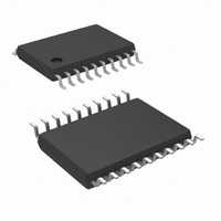
LMX2434TMX/NOPB National Semiconductor, LMX2434TMX/NOPB Datasheet - Page 40

LMX2434TMX/NOPB
Manufacturer Part Number
LMX2434TMX/NOPB
Description
IC SYNTHESIZER DUAL 5GHZ 20TSSOP
Manufacturer
National Semiconductor
Series
PLLatinum™r
Type
PLL Frequency Synthesizerr
Datasheet
1.LMX2433SLEXNOPB.pdf
(49 pages)
Specifications of LMX2434TMX/NOPB
Pll
Yes with Bypass
Input
CMOS
Output
CMOS
Number Of Circuits
1
Ratio - Input:output
3:2
Differential - Input:output
Yes/No
Frequency - Max
5GHz, 2.5GHz
Divider/multiplier
No/No
Voltage - Supply
2.25 V ~ 2.75 V
Operating Temperature
-40°C ~ 85°C
Mounting Type
Surface Mount
Package / Case
20-TSSOP
Frequency-max
5GHz
For Use With
LMX2434EVAL - EVALUATION BOARD FOR LMX2434
Lead Free Status / RoHS Status
Lead free / RoHS Compliant
Other names
LMX2434TMX
www.national.com
Reg
R1
R1
2.0 Programming Description
2.4.3 RF_CPG - RF Synthesizer Charge Pump Current Gain (R0[19])
The RF_CPG bit controls the RF synthesizer’s charge pump gain. Two gain levels are available.
2.4.4 RF_CPT - RF Synthesizer Charge Pump TRI-STATE (R0[20])
The RF_CPT bit allows the charge pump to be switched between a normal operating mode and a high impedance output state.
This happens asynchronously with the change in the RF_CPT bit.
Furthermore, the RF_CPT bit operates in conjuction with the RF_PD bit to set a synchronous or an asynchronous powerdown
mode. Refer to Section 2.5.4 for more details on how to program the RF_PD bit.
2.4.5 RF_RST - RF Synthesizer Counter Reset (R0[21])
The RF_RST bit resets the RF_A, RF_B and RF_R counters. After removing the reset, the RF_A and RF_B counters resume
counting in close alignment with the RF_R counter. The maximum error is one prescaler cycle.
2.5 R1 REGISTER
The R1 register contains the RF_A, RF_B, RF_P, and RF_PD control words. The RF_A and RF_B control words are used to setup
the programmable feedback divider. The detailed descriptions and programming information for each control word is discussed
in the following sections.
2.5.1 LMX243x RF Synthesizer Swallow Counter
2.5.1.1 RF_A[3:0] - LMX2430/33 RF Synthesizer Swallow Counter (A Counter) (R1[6:3])
The RF_A control word is used to setup the RF synthesizer’s A counter. For both the LMX2430 and LMX2433, the A counter is
a 4-bit swallow counter used in the programmable feedback divider. The RF_A control word can be programmed to values ranging
from 0 to 15.
RF_
RF_
PD
PD
23
Divide Ratio
RF_
RF_
22
P
P
15
Control Bit
Control Bit
Control Bit
0
1
•
RF_CPG
RF_CPT
RF_RST
21
20
19
18
Register Location
Register Location
Register Location
17
3
0
0
1
R0[19]
R0[20]
R0[21]
•
16
RF_B[13:0]
LMX2434
15
LMX2430/33
RF_B[14:0]
DATA[20:0] FIELD
14
(Continued)
RF Charge Pump
Current Gain
RF Charge Pump
TRI-STATE
RF Counter Reset
13
Description
Description
Description
2
0
0
1
12
•
40
11
LMX2430/33
RF_A[3:0]
10
RF Charge Pump
Normal Operation
RF_A, RF_B and
RF_R
Normal Operation
9
1 mA
LOW
8
0
0
0
1
0
0
1
•
7
Function
Function
Function
6
RF_A[4:0]
LMX2434
LMX2430/33
RF Charge Pump
Output in High
Impedance State
RF_A, RF_B and
RF_R
Reset
RF_A[3:0]
5
4
HIGH
4 mA
1
1
1
3
0
0
1
1
•
2
0
0
ADDRESS
FIELD
[2:0]
1
0
0
0
1
1


