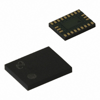
LMX2470SLEX National Semiconductor, LMX2470SLEX Datasheet - Page 32

LMX2470SLEX
Manufacturer Part Number
LMX2470SLEX
Description
IC PLL DELTA-SIGMA 24LAMUCSP
Manufacturer
National Semiconductor
Type
PLL Frequency Synthesizer, Delta Sigmar
Datasheet
1.LMX2470SLEXNOPB.pdf
(36 pages)
Specifications of LMX2470SLEX
Pll
Yes with Bypass
Input
CMOS
Output
CMOS
Number Of Circuits
1
Ratio - Input:output
3:3
Differential - Input:output
Yes/No
Frequency - Max
2.6GHz
Divider/multiplier
Yes/Yes
Voltage - Supply
2.25 V ~ 2.75 V
Operating Temperature
-40°C ~ 85°C
Mounting Type
Surface Mount
Package / Case
24-Laminate UTCSP
Frequency-max
2.6GHz
For Use With
LMX2470EVAL - EVALUATION BOARD FOR LMX2470
Lead Free Status / RoHS Status
Lead free / RoHS Compliant
Other names
*LMX2470SLEX
*LMX2470SLEX/NOPB
LMX2470SLEXCT
*LMX2470SLEX/NOPB
LMX2470SLEXCT
Available stocks
Company
Part Number
Manufacturer
Quantity
Price
www.national.com
REGISTER 23 22 21 20 19
Programming Description
2.7 R6 REGISTER
2.7.1 MUX[3:0] Frequency Out & Lock Detect MUX
These bits determine the output state of the Ftest/LD pin.
2.7.2 OSC -- Differential Oscillator Mode Enable
This bit selects between single-ended and differential mode for the OSCin and OSCout* pins. When this bit is set to 0, the RF R
and IF R counters are driven in a single-ended fashion through the OSCin pin. Note that the OSCin and OSCout* pin can not be
used to drive a crystal. When this bit is set to 1, the OSCin and OSCout* pins are used to drive these R counters differentially.
In some cases, spur performance may be better when this is set to differential mode, even if the R counters are being driven in
a single-ended fashion. Current consumption in differential mode is slightly higher than when in single-ended mode.
2.7.3 OSC2X -- Oscillator Doubler Enable
When this bit is set to 0, the oscillator doubler is disabled TCXO frequency presented to the IF R counter is unaffected. Phase
noise added by the doulber is negligible.
2.7.4 ATPU -- PLL Automatic Power Up
This word enables the PLLs to be automatically powered up when their respective registers are written to. Note that since the IF
Powerdown bit is in the IF register, there is no need to have an ATPU function activated by the R2 word.
R6
0
0
0
0
0
0
0
0
1
1
1
1
1
1
1
1
ATPU
0
1
2
3
0
0
0
0
0
1
1
1
1
0
0
0
0
1
1
1
1
0
MUX[3:0]
0
0
0
0
1
1
0
0
1
1
0
0
1
1
0
0
1
1
0
DATA[19:0] ( Except for the RF_N Register, which is [22:0] )
CPT
Powers up when R0 is written to
Powers up when R0 is written to
RF_
18
0
1
0
1
0
1
0
1
0
1
0
1
0
1
0
1
CPP
RF_
17
No auto power up
(Continued)
RF PLL
CPT
IF_
16
High Impedance
Output Type
Open Drain
Open Drain
Open Drain
CPP
IF_
Push-Pull
Push-Pull
Push-Pull
Push-Pull
Push-Pull
Push-Pull
Push-Pull
Push-Pull
Push-Pull
Push-Pull
Push-Pull
Push-Pull
15
FDM FM[1:0]
14
32
13
Reserved
12 11 10
General purpose output, Logical “High” State
General purpose output, Logical “Low” State
ATPU
[1:0]
Powers up when R0 is written to
RF & IF Analog Lock Detect
RF & IF Analog Lock Detect
OSC
RF & IF Digital Lock Detect
2X
RF R Divider divided by 2
RF N Divider divided by 2
IF R Divider divided by 2
IF N Divider divided by 2
9
RF Analog Lock Detect
RF Analog Lock Detect
RF Digital Lock Detect
IF Analog Lock Detect
IF Analog Lock Detect
IF Digital Lock Detect
Output Description
OSC
No auto power up
No auto power up
8
Disabled
IF PLL
7 6 5 4
MUX
[3:0]
C3 C2 C1 C0
3
1
2
0
1
1
0
1


