179610-1 TE Connectivity, 179610-1 Datasheet - Page 5
179610-1
Manufacturer Part Number
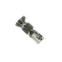
179610-1
Description
AMP CT CRIMP-2 REC CONT. L/P
Manufacturer
TE Connectivity
Specifications of 179610-1
Product Type
Contact
Termination Method To Wire/cable
Crimp
Contact - Rated Current (a)
2
Operating Voltage Reference
AC/DC, AC, DC
Operating Voltage (vac)
125
Operating Voltage (vdc)
125
Wire/cable Size (awg)
26 – 30
Mating Retention
Without
Contact Type
Socket
Contact Plating, Mating Area, Material
Pre-Tin
Rohs/elv Compliance
RoHS compliant, ELV compliant
Lead Free Solder Processes
Not relevant for lead free process
Rohs/elv Compliance History
Always was RoHS compliant
Operating Temperature (°c [°f])
-30 – +105 [-22 – +221]
Applies To
Wire/Cable
Accepts Wire Insulation Diameter, Range (mm [in])
0.65 – 1.35 [0.0255 – 0.053]
Application Use
Wire-to-Board, Wire-to-Board / Wire-to-Wire, Wire-to-Wire
Contact Transmits (typical Application)
Signal (Data)
Packaging Method
Loose Piece


ASHL-0005- ES REV B
3.8.1 (6)
3.8.1 (7)
3.8.1 (8)
3.8.2 (1)
3.8.2 (2)
3.8.2 (3)
3.8.2 (4)
Para.
Panel Mounting
Force (To be
applied to post
header for relay
use)
Panel Retention
Force
Confirmation of
Product
Termination
Resistance
(Low Level)
Dielectric
Strength
Insulation
Resistance
Temperature
Rising vs.
Current
Test Items
AMP Shanghai Ltd.
Tyco Electronics
49.0N Max.
83.3N Min.
Product shall be confirming to the
requirements of applicable product drawing
and Application Specification 114-5179.
10 m Max. (Initial)
20 m Max. (Final)
Connector must withstand test potential of 1.0
kV (AC) for 1 minute. Current leakage must
be 5.0mA Max.
1000 M Min. (Initial)
30
Fig. 3.
o
C max. under loaded specified current. See
Electrical Performance Requirements
Fig. 2 (To be continued)
Requirements
5 of 11
PAGE
Document No.
108-5408
By using AMP recommended
panel cut-out layout
dimensions, specified in AMP
Customer Drawing, measure the
force required to mount header
into the panel. Loading is made
from the punch entering
direction of the cut-out hole.
See Fig. 6.
By using AMP recommended
panel cut-out layout
dimensions, specified in AMP
Customer Drawing, measure the
force required to dislodge
header from the cut-out hole.
AMP Spec. 109-49.
Visually, dimensionally and
functionally inspected per
applicable inspection plan.
Subject mated contacts
assembled in housing to closed
circuit current of 50mA Max. at
open circuit voltage of 50mV
Max. See Fig. 3.
AMP Spec. 109-5306.
Measure by applying test
potential between the adjacent
contacts, and between the
contacts and ground in the
mated connector assembly.
(Measure on housing surface.)
MIL-STD-202, Method 301.
Measure by applying test
potential between the adjacent
contact, and between the
contacts and ground in the
mated connector assembly.
MIL-STD-202, Method 302,
Condition B.
Measure temperature rising by
energized current probing on
the tine area of the post.
AMP Spec. 109-5310.
Procedures
REV
B
LOC
ES
Related parts for 179610-1
Image
Part Number
Description
Manufacturer
Datasheet
Request
R

Part Number:
Description:
REPLACEMENT SOCKET W/GRND FORPROTEXRUBBE
Manufacturer:
DANIEL WOODHEAD


Part Number:
Description:
Printers THERMAL PRINTER HS-SLEEVE MARKER
Manufacturer:
TE Connectivity


Part Number:
Description:
High Speed / Modular Connectors 30P HEADER ASSY
Manufacturer:
TE Connectivity
Datasheet:

Part Number:
Description:
High Speed / Modular Connectors REC 6X005P R/A LT B-PLANE HS3
Manufacturer:
TE Connectivity
Datasheet:

Part Number:
Description:
High Speed / Modular Connectors 2MM HM RCPT 50P R/A AU
Manufacturer:
TE Connectivity
Datasheet:

Part Number:
Description:
High Speed / Modular Connectors 2MM HM RCPT 50P R/A AU
Manufacturer:
TE Connectivity
Datasheet:


Part Number:
Description:
Manufacturer:
TE Connectivity
Datasheet:


Part Number:
Description:
Manufacturer:
TE Connectivity
Datasheet:

Part Number:
Description:
Manufacturer:
TE Connectivity
Datasheet:

Part Number:
Description:
Manufacturer:
TE Connectivity
Datasheet: