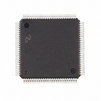
LM9832CCVJD National Semiconductor, LM9832CCVJD Datasheet - Page 14

LM9832CCVJD
Manufacturer Part Number
LM9832CCVJD
Description
IC SCANNER CLR USB IMAGE 100TQFP
Manufacturer
National Semiconductor
Datasheet
1.LM9832CCVJD.pdf
(42 pages)
Specifications of LM9832CCVJD
Number Of Bits
14
Number Of Channels
3
Voltage - Supply, Analog
5V
Voltage - Supply, Digital
5V
Package / Case
100-TQFP, 100-VQFP
Lead Free Status / RoHS Status
Contains lead / RoHS non-compliant
Power (watts)
-
Other names
*LM9832CCVJD
Available stocks
Company
Part Number
Manufacturer
Quantity
Price
Company:
Part Number:
LM9832CCVJD
Manufacturer:
Texas Instruments
Quantity:
10 000
Register Listing
Address
SENSOR PIXEL CONFIGURATION
PIXEL DATA RANGE TO PROCESS
COLOR MODE SETTINGS
RESERVED
1C
1D
1E
1F
20
21
22
23
24
25
26
27
28
Optical Black Pixels Start
Optical Black Pixels End
Active Pixels Start - MSB
Active Pixels Start - LSB
Line End - MSB
Line End - LSB
Data Pixels Start - MSB
Data Pixels Start - LSB
Data Pixels End - MSB
Data Pixels End - LSB
AFE Operation
3 Channel or 1 Channel
1 Channel Grayscale Input Source
(1 Channel Color always uses the
Blue Channel as the input)
TR
(3 Channel Line Rate Mode only)
TR
(3 Channel Line Rate Mode only)
TR
(3 Channel Line Rate Mode only)
3 Channel Line Rate TR
(3 Channel Line Rate Mode only)
3 Channel Line Rate TR
(3 Channel Line Rate Mode only)
3 Channel Line Rate TR
(3 Channel Line Rate Mode only)
Triple TR output
Reserved
RED
GREEN
BLUE
(=TR1) position
(=CP2) position
(=TR2) position
(Continued)
Function
RED
GREEN
BLUE
drop
drop
drop
D
7
n n n n n n n n n pixels (0 - 255)
n n n n n n n n n pixels (0 - 255)
n n n n n n n n
n n n n n n n n
n n n n n n n n
n n n n n n n n
0
1
0 0 0 0 0 0 0 0 Write 00 to this register
D
6
0
1
0
1
D
n n n n n n n pixels (0 - 16383)
n n n n n n
n n n n n n
n n n n n n n pixels (Data Pixels Start - [Line End - 20])
0
1
0 0
0 1
1 0
1 1
5
D
0 0
0 1
1 0
1 1
4
14
D
3
0 0
0 1
1 0
1 1
D
0 0 0 3 Channel Pixel Rate Color
0 0 1 3 Channel Line Rate Color
1 0 0 1 Channel Grayscale
1 0 1 1 Channel Color
2
D
0 0 Do not drop any TR
0 1 Drop 1 TR
1 0 Drop 2 TR
1 1 N/A
1
D
0
Set to the same value as register Data Pixels Start.
n pixels (0 - 16383)
This selects the pixel count at which the current line is
ended and the next line begins. This determines the
integration time of one line.
n pixels (Active Pixels Start - 16383)
This selects the start of the range of pixels transmitted
to the PC and determines the pixel location where
offset and shading correction begins (pixel 0 in the
DataPort). This value must be >= Active Pixels Start
This selects the end of the range of pixels transmitted
to the PC. This value must be <= [Line End - 20]
Red Channel
Green Channel
Blue Channel
N/A
1st TR pulse position (inside Ø1 high)
2nd TR pulse position (inside Ø1 low)
1st TR pulse position (inside Ø1 high)
2nd TR pulse position (inside Ø1 low)
1st TR pulse position (inside Ø1 high)
2nd TR pulse position (inside Ø1 low)
Do not drop any TR
Drop 1 TR
Drop 2 TR
N/A
Do not drop any TR
Drop 1 TR
Drop 2 TR
N/A
Normal operation
Outputs single TR pulse on TR1, TR2, and CP2 pins
RED
RED
GREEN
GREEN
BLUE
BLUE
pulse (double integration time)
pulses (triple integration time)
pulse (double integration time)
pulses (triple integration time)
pulse (double integration time)
pulses (triple integration time)
RED
GREEN
BLUE
Value
pulses
pulses
pulses
www.national.com


