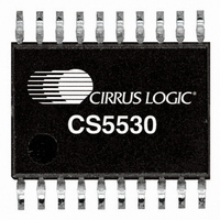
CS5530-ISZ Cirrus Logic Inc, CS5530-ISZ Datasheet - Page 12

CS5530-ISZ
Manufacturer Part Number
CS5530-ISZ
Description
IC ADC 24BIT 1CH W/LNA 20SSOP
Manufacturer
Cirrus Logic Inc
Datasheet
1.CS5530-ISZ.pdf
(36 pages)
Specifications of CS5530-ISZ
Number Of Converters
1
Package / Case
20-SSOP
Number Of Bits
24
Sampling Rate (per Second)
3.84k
Data Interface
Serial
Power Dissipation (max)
45mW
Voltage Supply Source
Analog and Digital, Dual ±
Operating Temperature
-40°C ~ 85°C
Mounting Type
Surface Mount
Number Of Adc Inputs
1
Architecture
Delta-Sigma
Conversion Rate
6.25 SPs to 3840 SPs
Resolution
24 bit
Input Type
Voltage
Interface Type
Serial (3-Wire)
Voltage Reference
2.5 V
Maximum Power Dissipation
500 mW
Maximum Operating Temperature
+ 85 C
Mounting Style
SMD/SMT
Minimum Operating Temperature
- 40 C
Lead Free Status / RoHS Status
Lead free / RoHS Compliant
For Use With
598-1158 - BOARD EVAL FOR CS5530
Lead Free Status / Rohs Status
Lead free / RoHS Compliant
Other names
598-1283-5
Available stocks
Company
Part Number
Manufacturer
Quantity
Price
Company:
Part Number:
CS5530-ISZ
Manufacturer:
CIRRUS
Quantity:
1 529
Part Number:
CS5530-ISZ
Manufacturer:
CIRRUS
Quantity:
20 000
Company:
Part Number:
CS5530-ISZR
Manufacturer:
CIRRUS
Quantity:
1 000
2.1.1 Analog Input Span
The full-scale input signal that the converter can dig-
itize is a function of the reference voltage connected
between the VREF+ and VREF- pins. The full-scale
input span of the converter is
((VREF+) – (VREF-))/(64Y), where 64 is the gain
of the amplifier and Y is 2 for VRS = 0, or Y is 1 for
VRS = 1. VRS is the Voltage Reference Select bit,
and must be set according to the differential voltage
applied to the VREF+ and VREF- pins on the part.
See section 2.3.4 for more details.
With a 2.5 V reference, the full-scale biploar input
range is equal to ±2.5/64, or about ±39 mV. Note
that these input ranges assume the calibration regis-
ters are set to their default values (i.e. Gain = 1.0 and
Offset = 0.0). The gain setting in the Gain Register
can be altered to map the digital codes of the con-
verter to set full scales from 1 mV to 40 mV.
2.1.2 Voltage Noise Density Performance
Figure 5 illustrates the measured voltage noise den-
sity versus frequency from 0.025 Hz to 10 Hz. The
device was powered with ±2.5 V supplies, using
30 Sps OWR, bipolar mode, and with the input
short bit enabled.
2.1.3 No Offset DAC
An offset DAC was not included in the CS5530 be-
cause the high dynamic range of the converter
eliminates the need for one. The offset register can
be manipulated by the user to mimic the function of
a DAC if desired.
12
1000
100
Figure 5. Measured Voltage Noise Density, 64x
10
1
0.025
0.10
Frequency (Hz)
1.00
10.00
2.2 Overview of ADC Register Structure
The CS5530 ADC has an on-chip controller, which
includes a number of user-accessible registers. The
registers are used to hold offset and gain calibration
results, configure the chip's operating modes, hold
conversion instructions, and to store conversion
data words. Figure 6 depicts a block diagram of the
on-chip controller’s internal registers.
The converter has 32-bit registers to function as the
offset and the gain calibration registers. These reg-
isters hold calibration results. The contents of these
registers can be read or written by the user. This al-
lows calibration data to be off-loaded into an exter-
nal EEPROM. The user can also manipulate the
contents of these registers to modify the offset or
the gain slope of the converter.
The converter includes a 32-bit configuration reg-
ister which is used for setting options such as the
power down modes, resetting the converter, short-
ing the analog input, enabling logic outputs, and
other user options.
The following pages document how to initialize the
converter and perform offset and gain calibrations.
Each of the bits of the configuration register is de-
scribed. Also the Command Register Quick Refer-
ence can be used to decode all valid commands (the
first 8-bits into the serial port).
2.2.1 System Initialization
The CS5530 provide no power-on-reset function.
To initialize the ADC, the user must perform a soft-
ware reset via the configuration register. Before
accessing the configuration register, the user must
insure serial port synchronization by using the Se-
rial Port Initialization sequence. This sequence re-
sets the serial port to the command mode and is
accomplished by transmitting at least 15 SYNC1
command bytes (0xFF hexadecimal), followed by
one SYNC0 command (0xFE hexadecimal). Note
that this sequence can be initiated at anytime to
reinitialize the serial port. To complete the system
and Operating Modes
CS5530
DS742F3


