AD7760BSVZ Analog Devices Inc, AD7760BSVZ Datasheet - Page 22
AD7760BSVZ
Manufacturer Part Number
AD7760BSVZ
Description
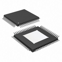
IC ADC 24BIT 2.5MSPS 64TQFP
Manufacturer
Analog Devices Inc
Datasheet
1.AD7760BSVZ.pdf
(36 pages)
Specifications of AD7760BSVZ
Data Interface
Parallel
Number Of Bits
24
Sampling Rate (per Second)
2.5M
Number Of Converters
1
Power Dissipation (max)
958mW
Voltage Supply Source
Analog and Digital
Operating Temperature
-40°C ~ 85°C
Mounting Type
Surface Mount
Package / Case
64-TQFP Exposed Pad
Resolution (bits)
24bit
Sampling Rate
2.5MSPS
Input Channel Type
Differential
Supply Voltage Range - Digital
2.375V To 2.625V
Supply Current
49mA
Lead Free Status / RoHS Status
Lead free / RoHS Compliant
Available stocks
Company
Part Number
Manufacturer
Quantity
Price
Company:

Part Number:
AD7760BSVZ
Manufacturer:
Analog Devices Inc
Quantity:
10 000
Part Number:
AD7760BSVZ
Manufacturer:
ADI/亚德诺
Quantity:
20 000
Company:
Part Number:
AD7760BSVZ-REEL
Manufacturer:
Analog Devices Inc
Quantity:
10 000


AD7760
AD7760 INTERFACE
READING DATA
When the AD7760 is outputting data at a 5 MHz output data
rate or less, the interface operates in a conventional mode, as
shown in Figure 2, using a 16-bit bidirectional parallel interface.
This interface is controlled by the RD /WR and CS pins. The 24-bit
conversion data is output in twos complement format. When a
new conversion result is available, an active low pulse is output
on the DRDY pin.
To read a conversion result from the AD7760, two 16-bit read
operations are performed. The DRDY pulse indicates that a new
conversion result is available. Both RD /WR and CS go low to
perform the first read operation. Shortly after both lines go low,
the data bus becomes active and the 16 most significant bits
(MSBs) of the conversion result are output. The RD /WR and CS
lines must return high for a full ICLK period before the second
read is performed. This second read contains the eight least
significant bits (LSBs) of the conversion result along with six
status bits. These status bits are shown in Table 7. Descriptions
of the other status bits are found in Table 17.
Table 7. Status Bits During Data Read
MSB
D7
DVALID
Shortly after RD /WR and CS return high, the data bus returns
to a high impedance state. Both read operations must be
completed before a new conversion result is available because
the new result overwrites the contents of the output register.
If a DRDY pulse occurs during a read operation, the data read
is invalid.
READING STATUS AND OTHER REGISTERS
The AD7760 features a number of programmable registers. To
read back the contents of these registers or the status register,
the user must first write to the control register of the device,
setting a bit that corresponds to the register to be read. The next
read operation outputs the contents of the selected register
instead of a conversion result. The AD7760 Registers section
provides more information on the relevant bits in the control
register.
SHARING THE PARALLEL BUS
By its nature, the high accuracy of the AD7760 makes it
sensitive to external noise sources. These include digital activity
on the parallel bus. For this reason, it is recommended that the
AD7760 data lines be isolated from the system data bus by
means of a latch or buffer to ensure all digital activity on the
D0 to D15 pins is controlled by the AD7760.
D6
OVR
D5
UFILT
D4
LPWR
D3
FILTOK
D2
DLOK
D1
0
LSB
D0
0
Rev. A | Page 22 of 36
If multiple synchronized AD7760 parts that share a properly
distributed common MCLK signal exist in a system, these parts
can share a common bus without being isolated from each
other. This bus can then be isolated from the system bus by a
single latch or buffer.
SYNCHRONIZATION
The SYNC input to the AD7760 provides a synchronization
function that allows the user to begin gathering samples of the
analog front-end input from a known point in time.
The SYNC function allows multiple AD7760s, operated from
the same MCLK, RESET , and SYNC signals, to be synchronized
so that each ADC simultaneously updates its output register.
The distribution of the signals that are common to each of the
devices that are to be synchronized is extremely important in
ensuring that the timing of each of the AD7760 devices is
correct, that is, that each AD7760 device sees the same digital
edges synchronously.
The SYNC signal is sensed on the falling edge of MCLK. On the
first falling edge of MCLK after SYNC goes logic low, the digital
filter sequencer is reset to 0. The filter is held in a reset state until
a falling edge of the MCLK senses SYNC logic high. The SYNC
signal must remain logic low for a minimum of four MCLK
cycles. Figure 46 shows the recommended timing for the SYNC
signal with respect to MCLK.
MCLK
The rising edge of SYNC should be coincident with the rising
edge of MCLK. Thus, the next falling edge of MCLK senses
SYNC logic high and takes the filter out of its reset state. By
applying this signal scheme to multiple ADCs using the same
MCLK and SYNC signals, all of the devices will gather input
samples synchronously.
Following a SYNC signal, the digital filter needs time to settle
before valid data can be read from the AD7760. The DVALID
status bit (D7 in Table 7) output with each conversion indicates
when valid data is being output by the converter. The time from
the rising edge of SYNC until the DVALID bit is asserted is
dependent on the filter configuration used. See the Theory of
Operation section and the values listed in Table 6 for details on
calculating the time until DVALID is asserted.
SYNC
MIN SYNC LOGIC LOW
4 ×
Figure 46. Recommended SYNC Timing
t
MCLK
DEVICE SYNCHRONIZED
FROM THIS POINT IN TIME
Related parts for AD7760BSVZ
Image
Part Number
Description
Manufacturer
Datasheet
Request
R

Part Number:
Description:
±1.7g Dual-Axis IMEMS Accelerometer Evaluation Board
Manufacturer:
Analog Devices Inc
Datasheet:

Part Number:
Description:
Inertial Sensor Evaluation System
Manufacturer:
Analog Devices Inc
Datasheet:
Part Number:
Description:
Manufacturer:
Analog Devices Inc
Datasheet:
Part Number:
Description:
Manufacturer:
Analog Devices Inc
Datasheet:
Part Number:
Description:
Manufacturer:
Analog Devices Inc
Datasheet:
Part Number:
Description:
Manufacturer:
Analog Devices Inc
Datasheet:
Part Number:
Description:
Manufacturer:
Analog Devices Inc
Datasheet:
Part Number:
Description:
Manufacturer:
Analog Devices Inc
Datasheet:
Part Number:
Description:
Manufacturer:
Analog Devices Inc
Datasheet:
Part Number:
Description:
Manufacturer:
Analog Devices Inc
Datasheet:
Part Number:
Description:
Manufacturer:
Analog Devices Inc
Datasheet:
Part Number:
Description:
Manufacturer:
Analog Devices Inc
Datasheet:
Part Number:
Description:
Manufacturer:
Analog Devices Inc
Datasheet: