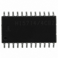
HI5714/4CBZ Intersil, HI5714/4CBZ Datasheet - Page 3

HI5714/4CBZ
Manufacturer Part Number
HI5714/4CBZ
Description
IC ADC 8-BIT 40MSPS 24-SOIC
Manufacturer
Intersil
Datasheet
1.HI57144CBZ.pdf
(14 pages)
Specifications of HI5714/4CBZ
Number Of Bits
8
Sampling Rate (per Second)
40M
Data Interface
Parallel
Number Of Converters
1
Power Dissipation (max)
375mW
Voltage Supply Source
Analog and Digital
Operating Temperature
0°C ~ 70°C
Mounting Type
Surface Mount
Package / Case
24-SOIC (0.300", 7.50mm Width)
Lead Free Status / RoHS Status
Lead free / RoHS Compliant
Absolute Maximum Ratings
V
V
V
V
V
I
Input Current, All Pins . . . . . . . . . . . . . . . . . . . . . . . . . . . . . . . . 1mA
Digital I/O Pins . . . . . . . . . . . . . . . . . . . . . . . . . . . . . OGND to V
Operating Conditions
Temperature Range
CAUTION: Stresses above those listed in “Absolute Maximum Ratings” may cause permanent damage to the device. This is a stress only rating and operation of the
device at these or any other conditions above those indicated in the operational sections of this specification is not implied.
NOTE:
Electrical Specifications
OUT
CLOCK (Referenced to DGND) (Note 2)
Logic Input Voltage Low, V
Logic Input Voltage High, V
Logic Input Current Low, I
Logic Input Current High, I
Input Impedance, Z
Input Capacitance, C
OE (Referenced to DGND)
Logic Input Voltage Low, V
Logic Input Voltage High, V
Logic Input Current Low, I
Logic Input Current High, I
V
Input Current Low, I
Input Current High, I
Input Impedance, Z
Input Capacitance, C
REFERENCE INPUT
Bottom Reference Range, V
Top Reference Range, V
Reference Range, V
Reference Current, I
Reference Ladder Resistance, R
R
Bottom Offset Voltage, V
V
Top Offset Voltage, V
V
1. θ
CCA
CCA
CCO
CCA
IN
HI5714/XCB . . . . . . . . . . . . . . . . . . . . . . . . . . . . . . . 0
OBTC
OTTC
IN
LADTC
, V
, Digital Pins . . . . . . . . . . . . . . . . . . . . . . . . . . . . . . . . . . . 10mA
JA
(Referenced to AGND)
, V
- V
- V
- V
CLK
CCD
is measured with the component mounted on an evaluation PC board in free air.
CCD
CCD
CCO
, V
, V
RT
. . . . . . . . . . . . . . . . . . . . . . . . . . . . . . . . . . . . . . ±0.3V
. . . . . . . . . . . . . . . . . . . . . . . . . . . . . . . . . . . . . . ±0.3V
. . . . . . . . . . . . . . . . . . . . . . . . . . . . . . . . . . . . . . ±0.3V
CCO
, V
RB
. . . . . . . . . . . . . . . . . . . . . . . . . . -0.3V to +6.0V
IN
IN
IL
IH
PARAMETER
REF
REF
, OE. . . . . . . . . . . . . . . . . . . . . . . -0.3V to +6.0V
IN
IN
OT
OB
RT
(V
IL
IL
IH
IH
IL
IL
IH
IH
RT
RB
- V
LAD
3
RB
V
CCA
)
T
A
= 25
= V
o
CCD
C
= V
CCO
o
V
V
f
f
V
V
V
V
f
f
(Note 5)
(Note 5)
(Note 5)
(Note 5)
C to 70
CLK
CLK
IN
IN
= +5V; V
CLK
CLK
IL
IH
IN
IN
= 4.43MHz
= 4.43MHz
= 0.4V
= 2.7V
= 1.2V
= 3.5V
= 75MHz (Note 9)
= 75MHz (Note 9)
CCO
= 0.4V
= 2.7V
o
C
TEST CONDITION
HI5714
RB
= 1.3V; V
Thermal Information
Thermal Resistance (Typical, Note 1)
Maximum Junction Temperature (Plastic Package) . . . . . . . .150
Maximum Storage Temperature Range . . . . . . . . . . -65
Maximum Lead Temperature (Soldering 10s) . . . . . . . . . . . . .300
SOIC Package . . . . . . . . . . . . . . . . . . . . . . . . . . . . .
(SOIC - Lead Tips Only)
RT
= 3.6V; T
A
= 25
o
-400
-400
C, Unless Otherwise Specified
MIN
2.0
2.0
1.2
3.5
1.9
0
0
-
-
-
-
-
-
-
-
-
-
-
-
-
-
-
TYP
0.24
-300
100
240
255
136
480
4.5
1.3
3.6
2.3
10
14
10
2
0
-
-
-
-
-
-
-
-
V
V
MAX
300
180
0.8
0.8
1.6
3.9
2.7
CCD
CCD
20
-
-
-
-
-
-
-
-
-
-
-
-
-
-
o
θ
C to 150
JA
UNITS
µV/
µV/
Ω/
mA
mV
mV
kΩ
kΩ
µA
µA
pF
µA
µA
µA
µA
pF
(
75
Ω
V
V
V
V
V
V
V
o
o
o
o
C/W)
C
C
C
o
o
o
C
C
C


