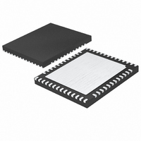
LTC2172CUKG-14#PBF Linear Technology, LTC2172CUKG-14#PBF Datasheet - Page 3

LTC2172CUKG-14#PBF
Manufacturer Part Number
LTC2172CUKG-14#PBF
Description
IC ADC 14BIT SER/PAR 65M 52-QFN
Manufacturer
Linear Technology
Datasheet
1.LTC2172IUKG-14PBF.pdf
(34 pages)
Specifications of LTC2172CUKG-14#PBF
Number Of Bits
14
Sampling Rate (per Second)
65M
Data Interface
Serial, Parallel
Number Of Converters
4
Power Dissipation (max)
419mW
Voltage Supply Source
Analog and Digital
Operating Temperature
0°C ~ 70°C
Mounting Type
Surface Mount
Package / Case
52-WFQFN Exposed Pad
Lead Free Status / RoHS Status
Lead free / RoHS Compliant
CONVERTER CHARACTERISTICS
PARAMETER
Resolution (No Missing Codes)
Integral Linearity Error
Differential Linearity Error
Offset Error
Gain Error
Offset Drift
Full-Scale Drift
Gain Matching
Offset Matching
Transition Noise
temperature range, otherwise specifi cations are at T
ANALOG INPUT
SYMBOL PARAMETER
V
V
V
I
I
I
I
t
t
CMRR
BW-3B
specifi cations are at T
IN(CM)
IN1
IN2
IN3
AP
JITTER
IN
IN(CM)
SENSE
Analog Input Range (A
Analog Input Common Mode (A
External Voltage Reference Applied to SENSE
Analog Input Common Mode Current
Analog Input Leakage Current (No Encode)
PAR/SER Input Leakage Current
SENSE Input Leakage Current
Sample-and-Hold Acquisition Delay Time
Sample-and-Hold Acquisition Delay Jitter
Analog Input Common Mode Rejection Ratio
Full-Power Bandwidth
A
= 25°C. (Note 5)
CONDITIONS
Differential Analog Input (Note 6)
Differential Analog Input
(Note 7)
Internal Reference
External Reference
Internal Reference
External Reference
External Reference
External Reference
IN
+
– A
The
IN
–
IN
l
)
+
denotes the specifi cations which apply over the full operating temperature range, otherwise
+ A
IN
–
)/2
A
CONDITIONS
1.7V < V
Differential Analog Input (Note 8)
External Reference Mode
Per Pin, 65Msps
Per Pin, 40Msps
Per Pin, 25Msps
0 < A
0 < PAR/SER < V
0.625 < SENSE < 1.3V
Figure 6 Test Circuit
= 25°C. (Note 5)
IN
The
l
l
l
l
l
+
, A
DD
–3.25
IN
l
MIN
–0.8
–2.5
–12
< 1.9V
14
–
denotes the specifi cations which apply over the full operating
< V
LTC2172-14
DD
DD
±0.3
±0.2
TYP
±20
±35
±25
1.2
±1
±3
–1
–1
±3
MAX
3.25
LTC2171-14/LTC2170-14
0.8
0.5
12
–2.75
MIN
–0.8
–2.5
–12
14
l
l
l
l
l
l
LTC2171-14
V
CM
±0.3
±0.2
TYP
±20
±35
±25
1.2
±1
±3
–1
–1
±3
0.625
MIN
– 100mV
–1
–3
–6
MAX
2.75
0.8
0.5
12
LTC2172-14/
1 to 2
1.250
0.15
TYP
V
–2.75
800
–0.8
–2.5
81
50
31
80
MIN
–12
CM
0
14
LTC2170-14
±0.3
±0.2
TYP
±20
±35
±25
1.2
±1
±3
–1
–1
±3
V
CM
1.300
MAX
+ 100mV
1
3
6
MAX
2.75
0.8
0.5
12
21721014fa
LSB
ppm/°C
ppm/°C
UNITS
UNITS
ps
μV/°C
3
%FS
%FS
%FS
LSB
LSB
V
MHz
Bits
RMS
RMS
mV
mV
P-P
μA
μA
μA
μA
μA
μA
dB
ns
V
V


